
Display system

A display system and display device technology, which is applied in the fields of instruments, electrical digital data processing, electrical components, etc., can solve the problems of user inconvenience, long distance between the user and the touch screen, and inconvenience.

Inactive Publication Date: 2012-10-03
BOE TECH GRP CO LTD +1
View PDF4 Cites 6 Cited by
  • Summary
  • Abstract
  • Description
  • Claims
  • Application Information

AI Technical Summary

Problems solved by technology

Proximity touch must be performed, which in some cases causes inconvenience to the user
For example, when a user uses a touch screen as a TV display device to watch TV programs, the distance between the user and the touch screen is often relatively long. operation, very inconvenient

Method used


Image

  • Display system
  • Display system
  • Display system

Examples


Embodiment approach 1

[0041] Considering that red light is relatively easy to obtain, in the embodiment of the present invention, the first beam and the second beam of the beam emitting device both use red laser light in the visible light region, the intensity of the first beam is the first intensity, and the second beam is the first intensity. The intensity of the two light beams is a second intensity, and the second intensity is greater than the first intensity.

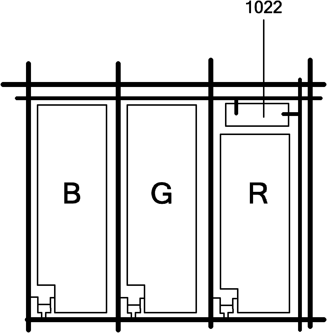
[0042] Please refer to image 3 The pixels on the color filter substrate are composed of three sub-pixels of red (R), green (G), and blue (B), and the photosensitive device 1022 is arranged on the position corresponding to the red sub-pixel on the array substrate, so The photosensitive device 1022 is configured to transmit its own address information to the processing device only when it senses the light beam of the second intensity. In order to avoid the influence of the first light beam on the photosensitive device 1022, the differen...

Embodiment approach 2

[0046] In the embodiment of the present invention, the first beam of the beam emitting device uses a green laser in the visible light region, and the second beam uses a red laser, and the second beam can be visible light or invisible light.

[0047] Similarly, taking the example that the pixels on the color filter substrate are composed of red, green and blue sub-pixels, the photosensitive device 1022 is disposed on the array substrate at a position corresponding to the red sub-pixel.

[0048] Assuming that the beam emitting device includes a double-stage button, when the double-stage button is lightly pressed, the emission of the green laser (first beam) is triggered, and the point A to be operated is searched on the display area of ​​the display device. After the positioning is completed, when the double-step button is pressed to the bottom, the red laser (second beam) is triggered to emit, and the photosensitive device 1022 corresponding to point A senses the second beam, an...


PUM


Abstract

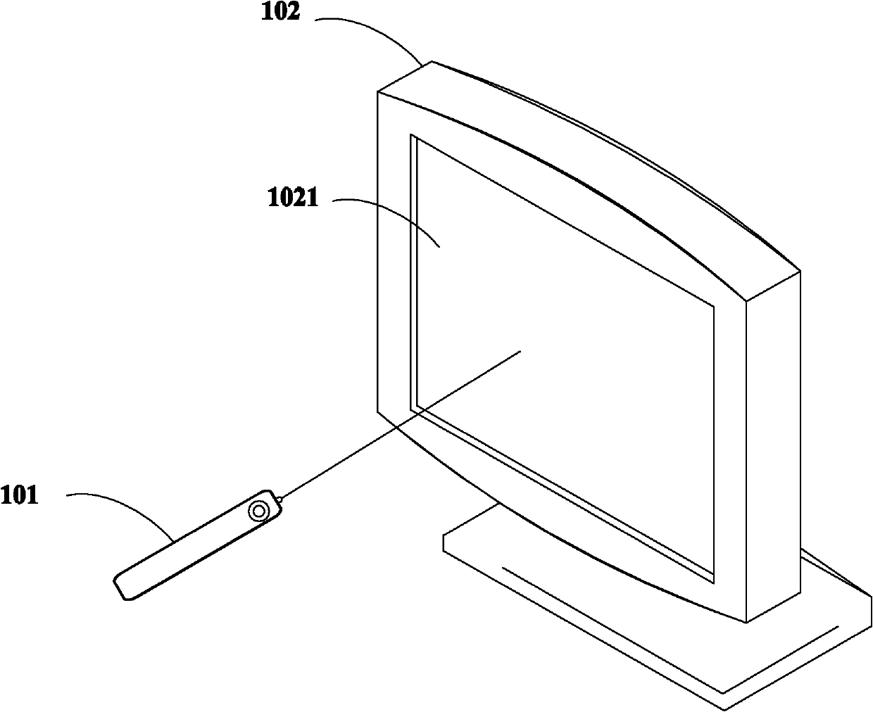
The invention provides a display system which comprises a light beam emission device and a display device, wherein the light beam emission device emits a first light beam for marking an input position and a second light beam for identifying the input position, the first light beam is a visible light, and the second light beam is different from the first light beam; the display device comprises a display area, a sensitization device which is distributed in the display area and a processing device which is coupled with the sensitization device, and the sensitization device is used for sensing the projection position of the second light beam on the display area according to the sensing result, and performs the corresponding operation according to the projection position of the second light beam. The display system can carry out the remote touch operation on the display device.

Description

technical field [0001] The present invention relates to the field of display technology, in particular to a display system. Background technique [0002] With the development of the times, touch screens are also more and more widely used. Most of the existing touch technologies use direct touch or short-distance light sensing to perform touch operations on the touch screen. A close touch is necessary, which in some cases causes inconvenience to the user. For example, when a user uses a touch screen as a TV display device to watch TV programs, the distance between the user and the touch screen is often relatively long. It is very inconvenient to operate. Contents of the invention [0003] In view of this, the present invention provides a display system capable of performing remote touch operations on a display device. [0004] In order to solve the above problems, the present invention provides a display system, including: a beam emitting device, which emits a first beam...

Claims


Application Information

Patent Timeline
Patent Type & Authority Applications(China)
IPC IPC(8): G06F3/01G06F3/042G06F3/033G06F3/0354
CPCG06F3/042G06F3/0304G06F3/0386G06F3/03545G06F3/0308G06F3/0412G06F3/03542H04N21/42204H04Q9/00
Inventor 袁剑峰张建楠林承武张振宇郑强
Owner BOE TECH GRP CO LTD
Learn More