
Dedicated machine for slotting both ends of steel pipe

A technology of steel pipe and machinery, which is applied in the field of special machinery for double-end grooving of steel pipes. It can solve the problems of steel pipe tower size deviation, low work efficiency, and high labor intensity, and achieve the effects of ensuring grooving accuracy, improving efficiency, and ensuring accuracy.

Active Publication Date: 2014-06-18
TANGSHAN KAIYUAN AUTOWELDING SYST
View PDF5 Cites 0 Cited by
  • Summary
  • Abstract
  • Description
  • Claims
  • Application Information

AI Technical Summary

Problems solved by technology

In the background technology, the grooving of steel pipes is usually done manually or with simple devices. The whole process includes manual scribing and manual cutting, and can only be operated at one end; the main problems are: 1. Manual single-end operation, work Low efficiency and high labor intensity; 2. The width and dimension accuracy requirements of the slot cannot be guaranteed, resulting in difficulty in installing the plug-in board or excessive gaps, increasing the rework time or the workload of welding the plug-in board; 3. Opening at both ends during single-ended operation The relative position of the groove is not easy to guarantee, resulting in the size deviation of the installation of the steel pipe tower; 4. The grooved cutting surface completed by manual or simple device is mostly centripetal, and the gap on one side after the inserting plate is installed is too large, which makes the welding workload of the inserting plate Increase

Method used


Image

  • Dedicated machine for slotting both ends of steel pipe
  • Dedicated machine for slotting both ends of steel pipe
  • Dedicated machine for slotting both ends of steel pipe

Examples


Embodiment Construction

[0022] Below in conjunction with accompanying drawing, the present invention will be further described through embodiment.

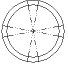
[0023] Refer to attached figure 2 , 3 , Background technology adopts the centripetal cutting steel pipe, the two ends of the steel pipe are slotted and then connected to the flashboard, and the gap on one side after the flashboard is installed is too large, which increases the workload of the flashboard welding.

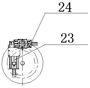
[0024] Refer to attached figure 1 , 4 , in an embodiment, a special mechanical machine for double-end slotting of steel pipes has a left-right symmetrical structure, a left moving trolley 10 is set on the left side of the base 1, a right moving trolley 20 is set on the right side of the base, and a linear guide rail is provided on the base, The wheels of the left mobile trolley and the right mobile trolley are respectively matched with the linear guide rail; the left axial slide seat 11, the left headstock 12 and the left cutting torch 16 a...


PUM


Abstract

The invention relates to a dedicated machine for slotting both ends of a steel pipe, belongs to the technical field of dedicated steel pipe processing equipment, and adopts the technical scheme that the dedicated machine adopts a bilaterally symmetrical structure; a left mobile trolley (10) is arranged on the left side of a base (1); a right mobile trolley (20) is arranged on the right side of the base (1); a linear guide rail is arranged on the base; the wheels of the left mobile trolley and those of the right mobile trolley are matched with the linear guide rail respectively; and a left axial sliding seat (11), a left main spindle box (12) and a left cutting torch (16) are arranged on the left mobile trolley. Adopting the both end cutting manner and the structural matching of a servomotor and a ball screw, the dedicated machine has the advantages that the efficiency is improved, and the precision is guaranteed; and a detection device can obtain the edge positions and the central positions of the ends of the steel pipe to slot a steel pipe with poor straightness, the requirement on the loading position of the steel pipe is lowered, and a radial adjusting sliding seat and a centering adjusting sliding seat are additionally arranged, so that the central positions of the steel pipe can be detected and tracked, a slotting surface and a cutting surface can be parallel to each other, and slotting precision is guaranteed.

Description

technical field [0001] The invention relates to a special machine for double-end grooving of steel pipes, belonging to the technical field of special equipment for steel pipe processing. Background technique [0002] At present, the steel pipe connection used in the steel pipe tower is mainly divided into two ways: flange and insert plate. The invention is a special equipment for slotting steel pipes connected by inserting plates. In the background technology, the grooving of steel pipes is usually done manually or with simple devices. The whole process includes manual scribing and manual cutting, and can only be operated at one end; the main problems are: 1. Manual single-end operation, work Low efficiency and high labor intensity; 2. The width and dimension accuracy requirements of the slot cannot be guaranteed, resulting in difficulty in installing the plug-in board or excessive gaps, increasing the rework time or the workload of welding the plug-in board; 3. Opening at ...

Claims


Application Information

Patent Timeline
Patent Type & Authority Patents(China)
IPC IPC(8): B23K7/00B23K7/10
Inventor 贺宗会冯忠友田丽萍朱金龙熊伟
Owner TANGSHAN KAIYUAN AUTOWELDING SYST
Learn More