
Continuous punching mould of movement bracket

A punching die and core technology, applied in the field of continuous punching die for core brackets, can solve the problems of unstable product quality, low work efficiency and high cost of use, reduce labor costs and mechanical costs, and improve work efficiency. Efficiency, the effect of reducing the defective rate

Inactive Publication Date: 2012-10-03
KUNSHAN WEIJIN HARDWARE PROD
View PDF6 Cites 6 Cited by
  • Summary
  • Abstract
  • Description
  • Claims
  • Application Information

AI Technical Summary

Problems solved by technology

The same is true of the core bracket mold currently in use. Although this mold has a simple structure and is easy to use, it has defects and problems such as low work efficiency, high use cost, and unstable product quality.

Method used


Image

  • Continuous punching mould of movement bracket

Examples


Embodiment Construction

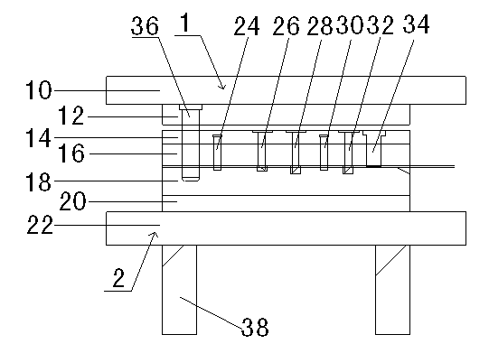
[0012] see figure 1 As shown, a continuous punching die for a core bracket of the present invention includes a corresponding upper mold 1 and a lower mold 2, wherein the upper mold 1 sequentially includes an upper mold frame plate 10, an upper mold backing plate 12, a discharge The plate backing plate 14 and the stripping plate 16, the lower mold includes the lower formwork 18, the lower mold backing plate 20 and the lower mold frame plate 22 in turn, and the special feature of the present invention is that a No. 1 punching hole is sequentially arranged on the stripping plate 16 Die 24, trimming die 26, No. 1 bending die 28, No. 2 punching die 30, No. 2 bending die 32 and forming die 34.

[0013] When making the blanking die of the present invention, preferably a guide post 36 is set in the stripper plate 16, the top of the guide post 36 extends into the upper die backing plate 12, and the bottom end of the guide post 36 extends to the below of the stripper plate 16, Holes (n...


PUM


Abstract

The invention discloses a continuous punching mould of a movement bracket, comprising an upper mould (1) and a lower mould (2), wherein the upper mould (1) and the lower mould (2) are correspondingly arranged, the upper mould (1) sequentially comprises an upper mould frame plate (10), an upper mould base plate (12), a stripper plate base plate (14) and a stripper plate (16), and the lower mould (2) sequentially comprises a lower mould plate (18), a lower mould base plate (20) and a lower mould frame plate (22). The continuous punching mould of the movement bracket is characterized in that a number one punching mould (24), a trimming mould (26), a number one bending mould (28), a number two punching mould (30), a number two bending mould (32) and a forming mould (34) are sequentially arranged on the stripper plate (16). In the invention, not only are the labor cost and the mechanical cost greatly reduced, but also the production stability is enhanced and the defective rate is lowered.

Description

technical field [0001] The invention relates to a punching die, in particular to a continuous punching die for a core bracket. Background technique [0002] At present, the punching die is generally composed of a punch and a die, and can also be composed of multiple punches and multiple dies, but only one punching process can be completed in one stroke of the punching machine. For example: the die-cutting die of the movement bracket is composed of multiple sets of single-engineering dies to produce a qualified product. The same is true of the core bracket mold used now. Although this mold is simple in structure and easy to use, it has the defects and problems of low work efficiency, high cost of use, and unstable product quality. Contents of the invention [0003] The technical problem to be solved by the present invention is to provide a continuous punching die for the core bracket with high working efficiency, low use cost and stable product quality. [0004] In order...

Claims


Application Information

Patent Timeline
Patent Type & Authority Applications(China)
IPC IPC(8): B21D37/10
Inventor 朱安邦
Owner KUNSHAN WEIJIN HARDWARE PROD
Learn More