Special molded case circuit breaker for prepayment electric energy meter

A prepaid electric energy meter, molded case circuit breaker technology, applied in the direction of instruments, coin-free or similar appliances, coin-operated equipment for rental items, etc. The protector cannot use the electric meter and other problems to achieve the effect of increasing the power isolation function and meeting the miniaturization effect.

Active Publication Date: 2014-12-10
SHANGHAI NOARK ELECTRIC
View PDF7 Cites 0 Cited by
  • Summary
  • Abstract
  • Description
  • Claims
  • Application Information

AI Technical Summary

Problems solved by technology

These existing special-purpose circuit breakers realize the tripping and tripping of power failure in arrears and all use the original tripper of the circuit breaker (such as a thermal tripper, or an electromagnetic tripper), so when starting a power failure tripping in arrears It is inevitable to generate a tripping current that trips the thermal release or the electromagnetic release. The magnitude of the tripping current is equivalent to the overload current of the thermal release or the short-circuit current of the electromagnetic release. The buckle current must flow through the control relay in the meter or in the circuit breaker, so there is still the problem that the relay is easily burned due to its small contact capacity
And these existing special circuit breakers can only be used in conjunction with one kind of electric meter, and cannot be compatible with other types of electric energy meters. For example, the circuit breaker of the Chinese invention patent No. ZL99110322.X cannot be used for the electric meter of the utility model patent No. ZL96241712.2 , the leakage protector of utility model patent No. ZL96241712.2 cannot be used for the ammeter of invention patent No. ZL99110322.X
It can be seen that in the development process of the new generation of special circuit breakers for prepaid electric energy meters, there are mainly the following three problems that need to be solved urgently: one is the safety, reliability, anti-theft and energy consumption of power-off control; The compatibility of special circuit breakers for various prepaid energy meters, and the third is the miniaturization of power-off control devices
Especially in the process of comprehensively solving the above-mentioned problems, there are two contradictions that are difficult to solve at the same time: the first is the isolation of the control circuit from the power supply and the signal power supply: in the control circuit of the prior art, the operating power supply adopts a non-isolated mode Directly refer to the two-phase power supply of L1 and N at the lower incoming line port of the circuit breaker. When the circuit breaker operates, the lower incoming line port also cuts off the power supply of L1 and N at the same time. Since the control power from the ammeter is also directly drawn from the L1 phase, When the circuit breaker is disconnected and the control voltage exists, there will be a large potential difference between the upper and lower inlet ports of L1 of the circuit breaker, and there will also be a small potential difference between L1 and N of the lower inlet line, which will affect the safety of users.
The second is the problem of limited size and space inside the circuit breaker: Due to the limitation of the size and space inside the circuit breaker, the technical risk and cost caused by changing the structure are relatively high. Therefore, the existing structure and space can only be used to meet the control requirements. While the circuit is miniaturized, it is necessary to increase the power isolation function

Method used


Image

  • Special molded case circuit breaker for prepayment electric energy meter
  • Special molded case circuit breaker for prepayment electric energy meter
  • Special molded case circuit breaker for prepayment electric energy meter

Examples


Embodiment Construction

[0020] The two embodiments of the special molded case circuit breaker for prepaid electric energy meters of the present invention and the various implementation modes contained in it will be described in detail below in conjunction with the accompanying drawings. The special molded case circuit breaker for prepaid electric energy meters of the present invention is not limited to the following embodiments and Description of the implementation.

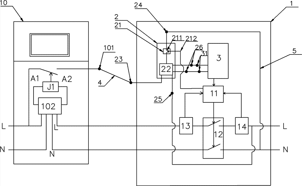
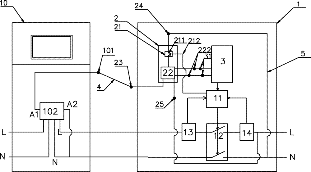
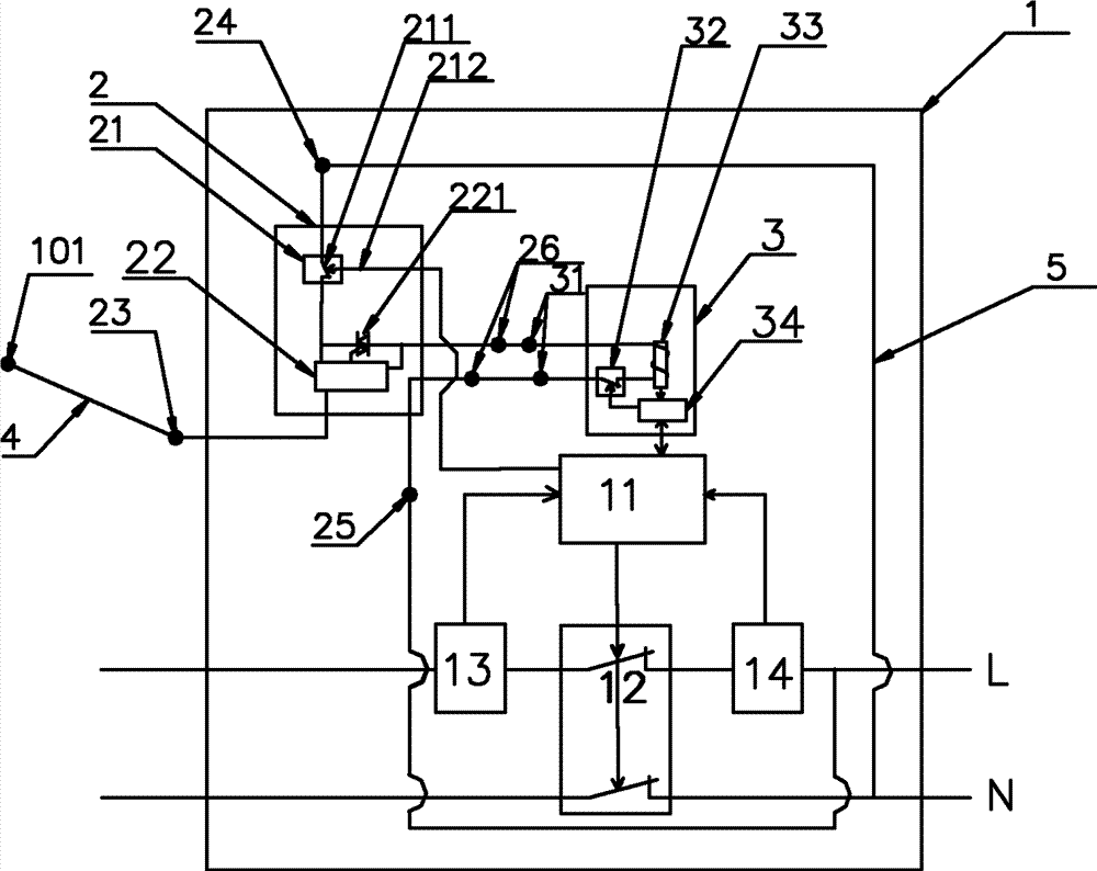
[0021] Figure 1 to Figure 5 It is the first embodiment of the special molded case circuit breaker for prepaid electric energy meter of the present invention, Figure 6 It is the second embodiment of the special molded case circuit breaker for prepaid electric energy meters of the present invention. The difference between the first and second embodiments is that the built-in control module 2 and the shunt release 3 of the first embodiment are respectively Embedded in the circuit breaker body 1 as an independent module unit; while the bui...


PUM


Abstract

The invention provides a special molded case circuit breaker for a prepayment electric energy meter. The special molded case circuit breaker comprises a circuit breaker body, a shunt release nested within the body, and a built-in control module. A switch device of the built-in control module is connected with a circuit breaker operation mechanism or the shunt release, and the switch on / switch off of the switch device is controlled by switch on and switch off actions of the operation mechanism or the shunt release module. A detection input terminal of the built-in control module is connected with a single output terminal of the electric energy meter, the switch device is serially connected between a control circuit and a neutral line access terminal, and the neutral connection terminal is connected with a neutral line of a main circuit, and a control output terminal of the control circuit is connected with a release control input terminal of the shunt release and controls a release device on the shunt release to trigger the circuit breaker operation mechanism to complete an open circuit operation. The built-in control module can be independently nested within the circuit breaker body or nested within the shunt release module to form reliable isolation between the circuit breaker and the single output terminal of the electric energy meter, and provides security guarantee for the interchange of each module unit and the operation of the circuit breaker.

Description

technical field [0001] The invention relates to a low-voltage circuit breaker with a shunt tripping function that can be used with a prepaid electric energy meter, in particular to a molded case circuit breaker dedicated to a prepaid electric energy meter. After receiving the control signal sent by the user's meter in arrears, the circuit breaker will open to disconnect the user end, so as to control the arrears users from being unable to get electricity. Background technique [0002] As we all know, the shunt release is a device for remote opening operation of the circuit breaker. Generally, it is realized by an independent auxiliary module of the circuit breaker, and the circuit breaker with the function of shunt trip does not use an independent shunt release. The module can realize the remote tripping control of the circuit breaker. Prepaid electric energy meters with remote meter reading function (hereinafter referred to as electric meters) are widely used in the transf...

Claims


Application Information

Patent Timeline
Patent Type & Authority Patents(China)
IPC IPC(8): H01H71/24G07F15/06
Inventor 林海生徐永富唐丰田唐芳
Owner SHANGHAI NOARK ELECTRIC
Why Eureka
Try Eureka