Remote control switch for lamp

A technology of remote control switches and lamps, which is applied in the direction of electric switches, electrical components, circuits, etc., can solve the problems of unreasonable structure, weak power generation capacity, inconvenient operation, etc., and achieve the effect of simple structure, large power generation, and high reliability

Inactive Publication Date: 2012-09-26
ZHEJIANG NORMAL UNIVERSITY
View PDF9 Cites 9 Cited by
  • Summary
  • Abstract
  • Description
  • Claims
  • Application Information

AI Technical Summary

Problems solved by technology

[0003] Aiming at the current situation that the existing lamp remote control switch cannot be popularized and applied due to reasons such as weak power generation capacity, inconvenient operation or unreasonable structure, the present invention provides a lamp remote control switch based on a spring piece that directly excites a piezoelectric vibrator to generate power.

Method used


Image

  • Remote control switch for lamp
  • Remote control switch for lamp
  • Remote control switch for lamp

Examples


Embodiment Construction

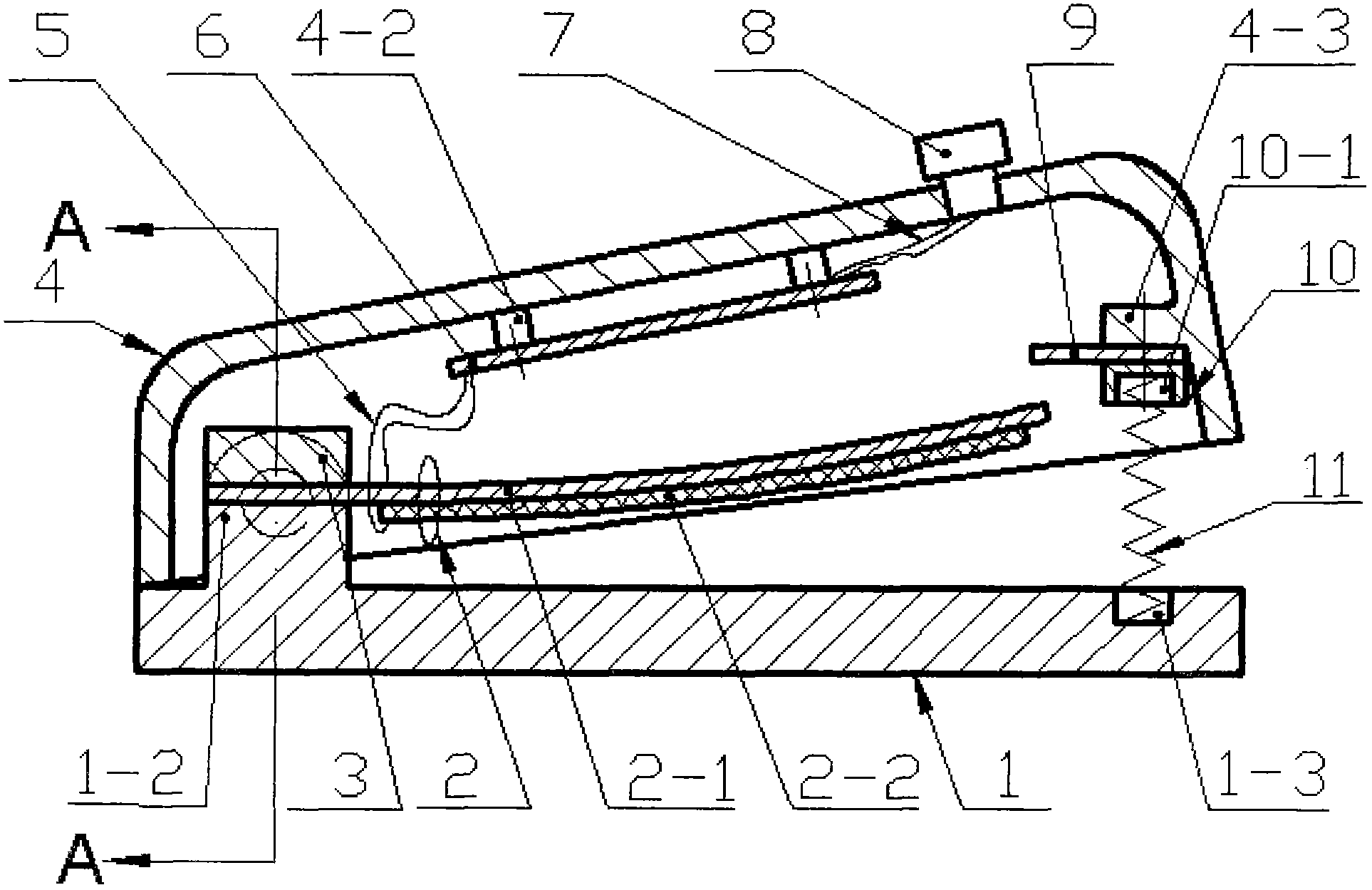
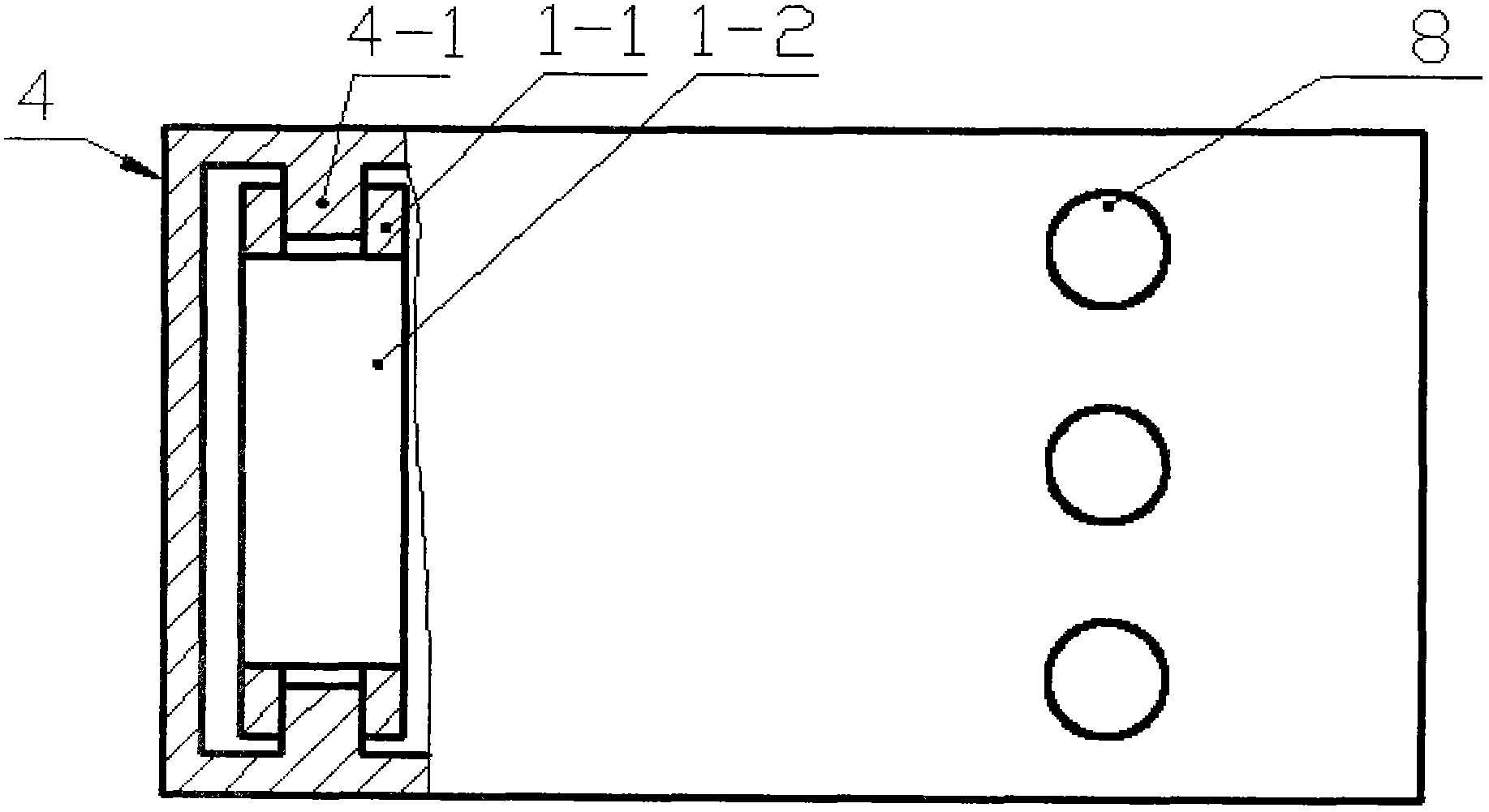
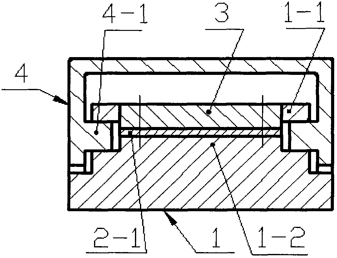
[0014] One end of the base 1 is provided with a pair of connecting ears 1-1 and a boss 1-2, and the other end is provided with a blind hole 1-3; On the platform 1-2, the piezoelectric vibrator 2 is formed by bonding the metal substrate 2-1 and the piezoelectric wafer 2-2; a pair of pin shafts 4-1 is provided at one end of the housing 4, and a support is provided at the upper end of the housing 4. Seat 4-2, the other end of the inside is provided with connecting plate 4-3, and button 8 is installed on the outer upper surface; The pin shaft 4-1 on the housing 4 is hinged with the connecting ear 1-1 on the base 1; the circuit board 6 It is installed on the support 4-2 of the housing 4 through screws, and the circuit board 6 is provided with a power conversion circuit and a signal transmission circuit. The wire group 7 is connected with the button 8; the spring sheet 9 is fixed on the connecting plate 4-3 of the housing 4 with screws through the pressing block 10, and the pressing...


PUM


Abstract

The invention relates to a remote control switch for a lamp, and belongs to the technical fields of new energy and electronic communication. A pair of connecting lugs and a lug boss are arranged at one end of a base, and a blind hole is formed at the other end of the base. One end of a piezoelectric vibrator is fixed on the lug boss of the base by a pressure plate. A pair of pin shafts is arranged at one end in a shell, a connecting plate is arranged at the other end in the shell, and keys are arranged on an upper surface outside the shell. The pin shafts on the shell are hinged with the connecting lugs on the base. A circuit board is arranged on a support of the shell. An electric energy conversion and signal transmission circuit is arranged on the circuit board, and is connected with the piezoelectric vibrator through a first wire group, and is connected with the keys through a second wire group. A spring piece is fixed on the connecting plate of the shell through a pressure block, and a blind hole is formed in the pressure block. The two ends of a resetting spring are crimped in the blind holes in the base and the pressure plate respectively. The remote control switch has the advantages that the spring piece arranged on the end part of the shell is directly used for stirring the flexural piezoelectric vibrator, and another moving element is not required; and the remote control switch is simple in structure, high in reliability and low in cost.

Description

technical field [0001] The invention belongs to the technical field of new energy and electronic communication, and in particular relates to a remote control switch for lamp control. Background technique [0002] The traditional fixed lamp switch is connected to the lamp through wires. Because wiring inside the wall is required, the construction and decoration costs are high, and it is difficult to change the position after it is determined. In recent years, with the increasing popularity of combination lamps, lamp switches have gradually transitioned from wall-mounted switches to portable or movable remote control. The current lamp remote control switches are basically powered by batteries, which cannot be used when the battery power is exhausted. At the same time, discarded batteries will also cause serious environmental pollution and waste of resources. For this reason, people have successively proposed various forms of lamp remote control switches powered by piezoelectr...

Claims


Application Information

Patent Timeline
IPC IPC(8): H01H13/20H02N2/18
Inventor 王淑云阚君武杨振宇蒋永华曾平程光明
Owner ZHEJIANG NORMAL UNIVERSITY
Why Eureka
Try Eureka