
Liquid crystal display device

A liquid crystal display device and liquid crystal panel technology, which is applied in nonlinear optics, instruments, optics, etc., can solve the problems of the display device not achieving narrow edge, visual error, etc., to ensure the appearance quality, reduce structural components, and realize narrow edge. effect of design

Active Publication Date: 2014-06-18
TCL CHINA STAR OPTOELECTRONICS TECH CO LTD
View PDF6 Cites 0 Cited by
  • Summary
  • Abstract
  • Description
  • Claims
  • Application Information

AI Technical Summary

Problems solved by technology

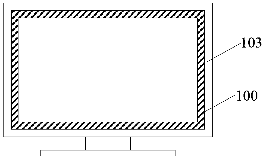
Because the front frame 100 is mostly dark, and the outer frame 103 is transparent, there will be visual errors, giving people the visual effect of narrowing the border, but the structure of the liquid crystal display device still does not achieve narrowing.

Method used


Image

  • Liquid crystal display device
  • Liquid crystal display device
  • Liquid crystal display device

Examples


Embodiment Construction

[0016] The technical solutions in the embodiments of the present invention will be clearly and completely described below in conjunction with the accompanying drawings in the embodiments of the present invention. Obviously, the described embodiments are only a part of the embodiments of the present invention, rather than all the embodiments. Based on the embodiments of the present invention, all other embodiments obtained by those of ordinary skill in the art without creative work shall fall within the protection scope of the present invention.

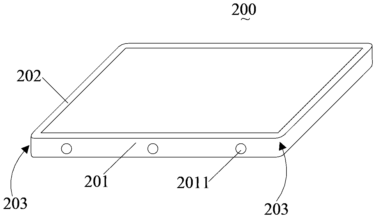
[0017] See image 3 , image 3 It is a schematic structural diagram of the front frame of the first embodiment of the present invention.

[0018] The front frame 200 includes a side plate 201 enclosing a rectangle and an extension portion 202 bent and extended from the edge of the side plate 201 to the inner side of the side plate 201. The four corners 203 of the side plate 201 are all arc-shaped chamfers. In this embodiment, the arc cham...


PUM


Abstract

The present invention discloses a front frame for a liquid crystal display device, comprising side plates enclosed in a rectangle, an extension part extending in buckling from an edge of the side plate to the inside of the side plate, and four angles of the side plate in relative to the rectangle are arc-shaped chamfers. The present invention also discloses a liquid crystal display device. In the present invention, four angles of the side plate are set to arc-shaped chamfers, thereby reducing structural components of the liquid crystal display device, implementing a narrowing design, and ensuring that appearance quality is not influenced.

Description

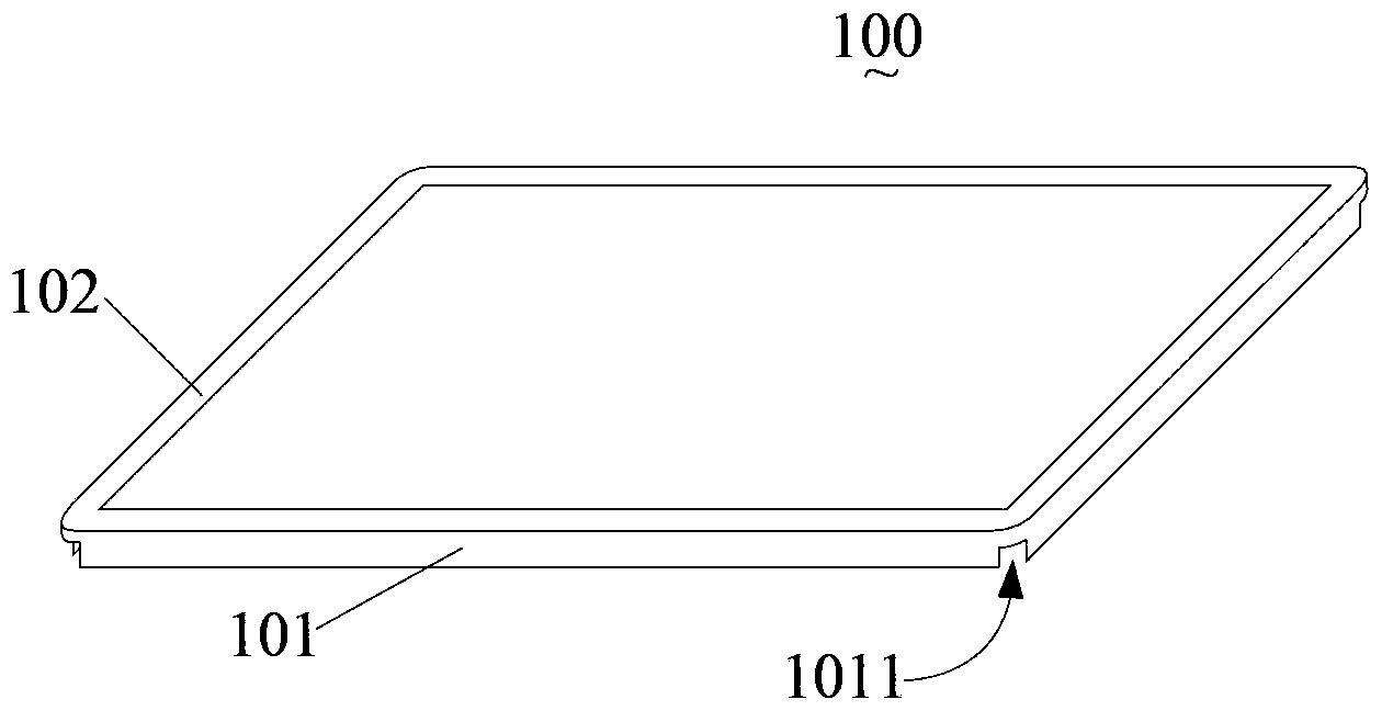
Technical field [0001] The present invention relates to the field of liquid crystal display, in particular to a liquid crystal display device. Background technique [0002] When designing the structure of the liquid crystal display device, a front frame is usually used to fix the liquid crystal panel to prevent it from jumping out. See figure 1 , figure 1 It is a schematic diagram of the structure of the front frame in the prior art. The front frame 100 includes a side plate 101 and an extension part 102, and the side plate 101 forms a rectangle. When the front frame 100 is formed, there are notches 1011 in the four corners of the side plate 101. In order to cover the gap 1011, a light-shielding tape is usually attached along the surface of the side plate 101. Further, please refer to figure 2 , figure 2 It is a schematic diagram of the structure of a prior art liquid crystal display device. The liquid crystal display device uses figure 1 The front frame shown. In order not...

Claims


Application Information

Patent Timeline
Patent Type & Authority Patents(China)
IPC IPC(8): G02F1/13
CPCG02F1/13G02F2001/13332G02F1/133308G02F1/13332
Inventor 唐国富
Owner TCL CHINA STAR OPTOELECTRONICS TECH CO LTD
Learn More