
Device and method for detecting microbending loss of optical fiber

An optical fiber and microbending technology, which is applied in the field of microbending loss detection, can solve the problems of adding optical fibers, poor accuracy, and low positioning accuracy, and achieves the effects of simple operation, good repeatability, and high accuracy

Active Publication Date: 2015-05-06
NANJING WASIN FUJIKURA OPTICAL COMM LTD
View PDF5 Cites 0 Cited by
  • Summary
  • Abstract
  • Description
  • Claims
  • Application Information

AI Technical Summary

Problems solved by technology

Many manufacturers are doing research on microbending loss, and have also proposed some in-factory inspection methods, but there are major defects: poor practicability, poor accuracy, and relatively poor repeatability
The disadvantages of this method are: (1) There will be errors when the optical fiber is wound into a 98mm circle. Different people may have different sizes and shapes when winding the circle, and the winding will increase the twist of the optical fiber and cause deviations in the fiber test data. , the repeatability will be reduced, and the accuracy will also be reduced (2) The use of tape also makes the force of the optical fiber uneven, and the formation of microbends is also inaccurate
(3) The gap on the rubber sheet that reduces the length of the marking circle by 8mm also increases the uncertainty
Therefore, the metal grid method also has the disadvantages of poor repeatability and accuracy.
(4) There are only two positioning columns, and the positioning accuracy is not high

Method used


Image

  • Device and method for detecting microbending loss of optical fiber
  • Device and method for detecting microbending loss of optical fiber

Examples


Embodiment 1

[0022] Embodiment 1 The structure of the device for detecting optical fiber microbending loss according to the present invention

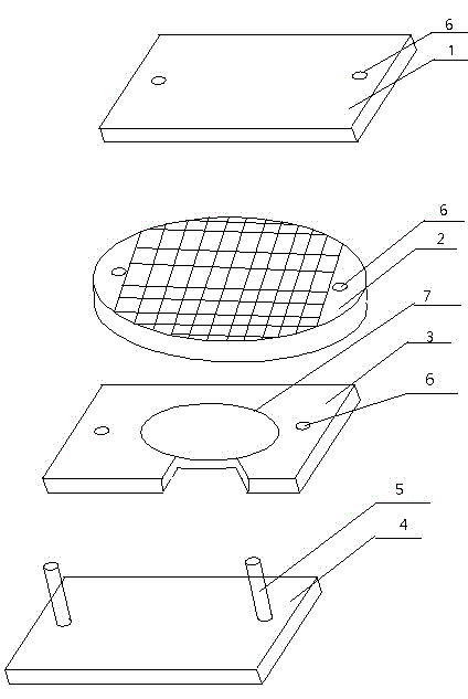
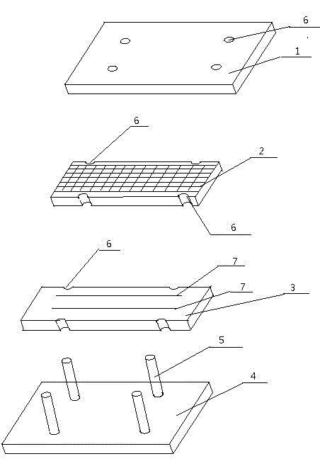
[0023] The device for detecting optical fiber microbending loss of the present invention includes a metal cover plate 1, a metal grid 2, a rubber plate 3 and a metal base 4 provided with a positioning column 5, the metal cover plate 1, the metal grid 2 and the rubber plate 3 are provided with positioning holes 6 that match the positioning columns 5, and two marking lines 7 with a distance of 20-30 mm and a length of 145-155 mm are also provided on the rubber plate 3. The metal grid 2 The length is the same as the marked line length.

[0024] There are four positioning columns 5 on the metal base 4, and four positioning holes 6 on the metal cover plate 1, the metal grid 2 and the rubber plate 3 respectively.

[0025] The metal grid 2 is rectangular.

Embodiment 2

[0026] Embodiment 2 Method for detecting optical fiber microbending loss by using the device of the present invention

[0027] In the detection process, in addition to the device for detecting the microbending loss of the optical fiber of the present invention, a pillar and an optical power meter are also required. The diameter of the column is 60-200 mm, preferably 60 mm.

[0028] The method for detecting optical fiber microbending loss using the device of the present invention is to place the device for detecting optical fiber microbending loss between the pillar and the optical power meter, and the rubber plate 3 is fixed on the metal base 4. The method also includes the following steps:

[0029] (1) Leave 40-50cm of the free end of the optical fiber to be tested to connect to the optical power meter, and then fix the subsequent optical fiber on one of the marking lines 7 with adhesive tape under the condition of no force, and then wind along the column Filter out the high...

Embodiment 3

[0035] Embodiment 3 The comparison between the method of the present invention and the original metal grid method to detect the microbending loss of optical fiber

[0036] 20 samples were taken from the same optical fiber, and tested by the method of the present invention and the original metal grid method, and the test data of the two methods were compared. In the optical power meter used (1310nm light source is generally used for multi-single-mode fiber, and 1550nm light source is generally used for single-mode fiber), the method of filtering out high-order film (loosely winding a circle on a column with a diameter of 60mm), rubber plate (with a hardness of 75 ), the metal grid (specification 70 mesh), and the weight of the metal cover are the same, only the weight of the weight added to the metal cover is changed, and the test results obtained are as follows:

[0037] Table 1 The test results when the weight of the heavy object on the metal cover is 2kg

[0038] ...


PUM


Abstract

The invention provides a device and method for detecting the microbending loss of an optical fiber, relating to the field of detection of optical fibers. The device comprises a metal cover plate, a metal mesh, a rubber plate and a metal base, wherein two marked lines with the spacing distance of 20-30 mm and the length of 145-155 mm are arranged on the rubber plate, and the length of the metal mesh is the same as that of the marked lines. The method for detecting the microbending loss of the optical fiber, provided by the invention, comprises the following steps of: reserving a free end from the optical fiber, connecting the free end with an optical power meter, fixing the optical fiber on one marked line, making a circle around posts by using the optical fiber, fixing the optical fiber on the other marked line, reserving another free end, and connecting the another free end with the optical power meter; sleeving the metal mesh on the metal base, sleeving the metal cover plate on the metal base, and recording a numerical value displayed by the optical power meter; adding a weight on the metal cover plate, and recording a numerical value displayed by the optical power meter; and obtaining a difference value of the two numerical values, thereby obtaining the microbending loss of the optical fiber. The device for detecting the microbending loss of the optical fiber, provided by the invention, is simple and convenient in operation; and the method is simple and accurate.

Description

technical field [0001] The invention relates to the field of optical fiber inspection, in particular to a method for detecting microbend loss in optical properties of optical fibers. Background technique [0002] The bending loss of optical fiber can be divided into microbending loss and macrobending loss. The routine inspection of optical fiber is to check the macrobending loss of optical fiber, and the microbending loss is not taken seriously by people. With the continuous research on optical fiber technology, it is found that the microbending loss has a certain influence on the performance of optical fiber. [0003] The so-called microbending loss is the effect of uneven stress on the optical fiber, such as when the optical fiber is subjected to side pressure or the temperature change of the sheathed optical fiber, the optical fiber axis is slightly irregularly bent, and the result is that the conduction mode is transformed into a radiation mode, resulting in light energy...

Claims


Application Information

Patent Timeline
Patent Type & Authority Patents(China)
IPC IPC(8): G01M11/02
Inventor 王小泉谢晓红赵强
Owner NANJING WASIN FUJIKURA OPTICAL COMM LTD
Learn More