
Slider for slide fastener

A technology for sliders and zippers, applied in the field of sliders for zippers, which can solve problems such as entry, slider sliding operation obstruction, etc.

Active Publication Date: 2012-09-19
YKK CORP
View PDF9 Cites 9 Cited by
  • Summary
  • Abstract
  • Description
  • Claims
  • Application Information

AI Technical Summary

Problems solved by technology

[0026] However, in the case of a conventional slider that can be pulled and pulled from the rear, when a slide fastener having the slider is installed and used on a product such as clothing or bags, the following problems have occurred: Other components such as thin cloth pieces that accidentally exist in the peripheral portion of the slider enter the above-mentioned insertion gap of the slider and are caught in the insertion gap
[0029] In addition, since other thin members are sandwiched by the slider as described above, there are disadvantages that clothing or bags are pulled by the other members, and that the sliding operation of the slider is hindered by the other members. , so it is necessary to eliminate such undesirable conditions

Method used


Image

  • Slider for slide fastener
  • Slider for slide fastener
  • Slider for slide fastener

Examples


Embodiment 1

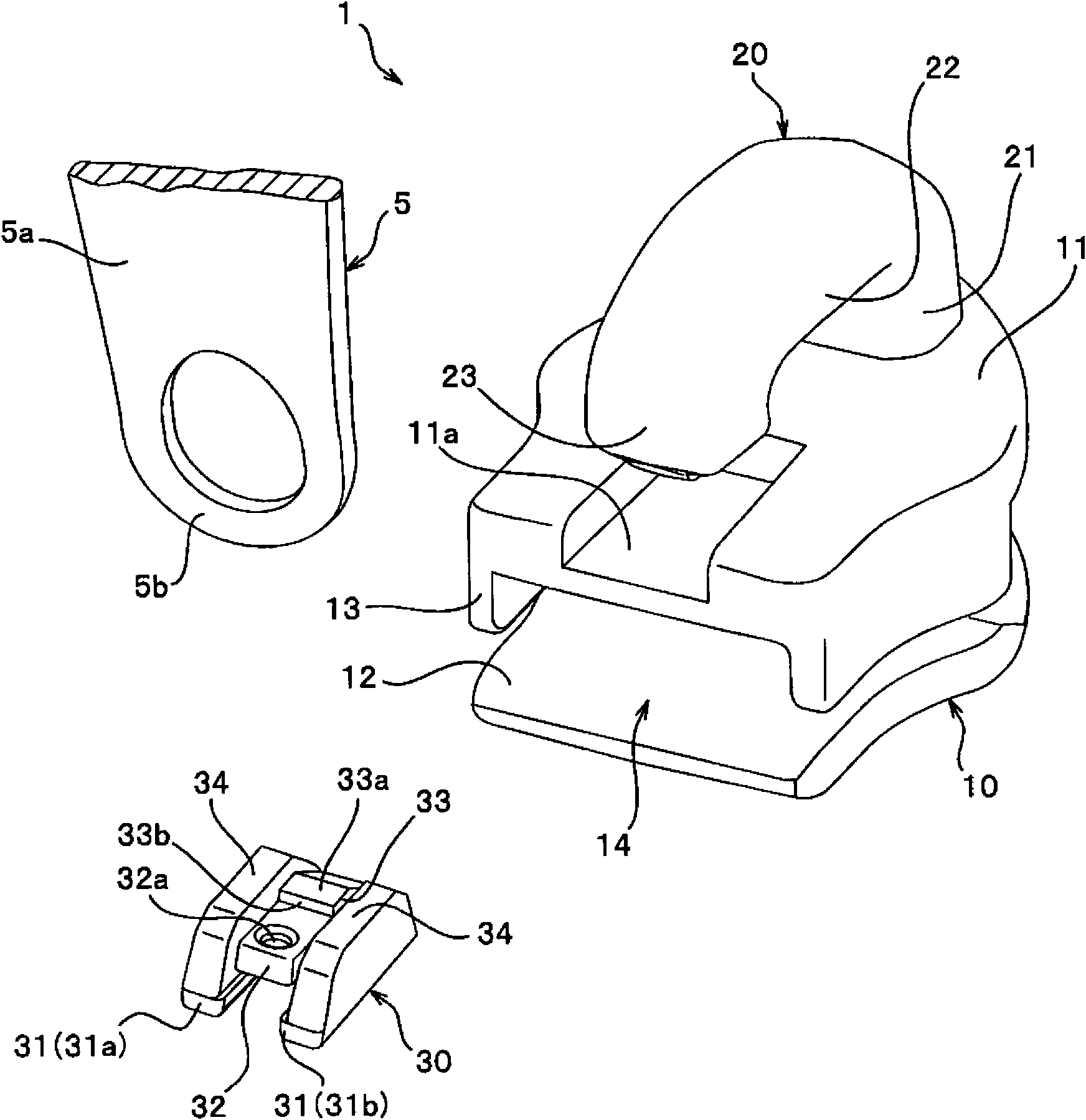
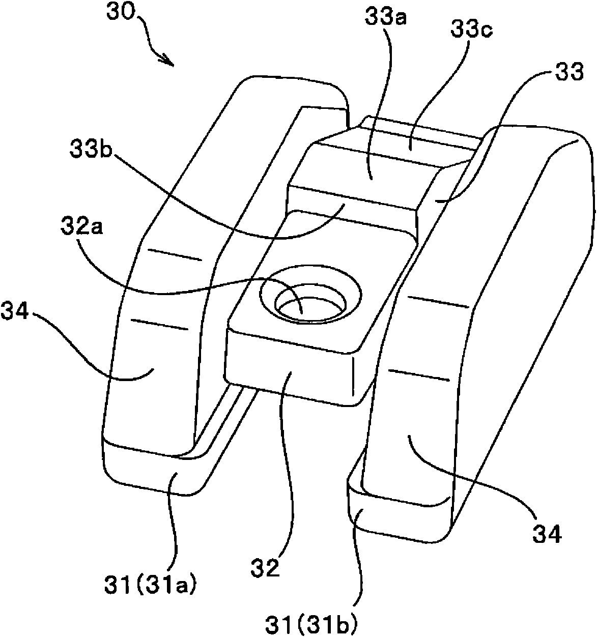
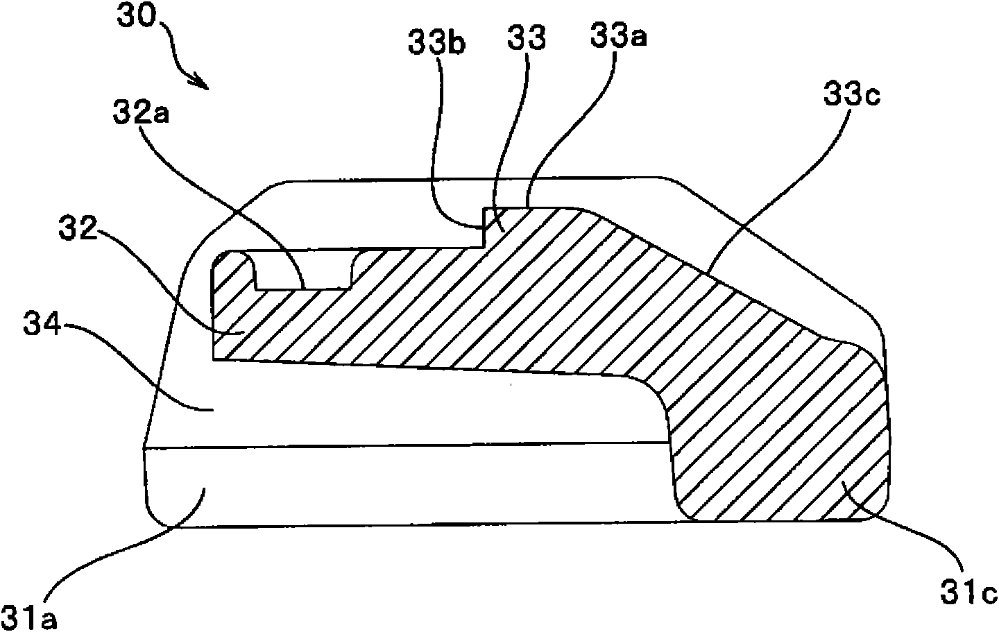
[0083] figure 1 It is an exploded perspective view of the slider for slide fasteners of the present Example 1, Figure 2 to Figure 4 is a diagram showing the latch member in the slider, Figure 5 as well as Image 6 It is a figure which shows the upper wing plate and the handle mounting rod in this slider.

[0084] In addition, in the following description, the slider sliding direction is defined as the front-rear direction, and in particular, the direction in which the slider moves in order to mesh the element row of the slide fastener is referred to as the front, and the direction in which the slider moves in order to separate the coil-shaped element row is referred to as the front. as the rear. Moreover, the height direction of a slider is prescribed|regulated as an up-down direction, especially the direction which attached the handle side with respect to the slider main body was made into upper direction, and the direction of the opposite side was made into downward di...

Embodiment 2

[0118] Figure 10 It is an exploded perspective view of the slider for slide fasteners of this Example 2. FIG. in addition, Figure 11 is a side view showing the locking member in the slider, Figure 12 It is a partial cross-sectional view of the slider main body and the handle mounting rod in the slider.

[0119] In addition, in the sliders of the second embodiment and the third embodiment to be described later, the members or parts having the same structure as the members or parts described in the above-mentioned first embodiment are denoted by the same reference numerals and omitted. illustrate.

[0120] The slider 2 for slide fasteners of the second embodiment includes a slider main body 40; a handle attachment rod 50 integrally formed in the slider main body 40 in a cantilever shape; a latch member 60 attached to the slider main body 40; Handlebar 5 on handlebar 50.

[0121]The slider main body 40 in the slider 2 includes: upper and lower wings 41 and 42 arranged sub...

Embodiment 3

[0144] Figure 18 It is a perspective view showing the locking member in the slider for slide fasteners of the third embodiment; Figure 19 It is a partial cross-sectional view which shows the state in which the handle is attached to the handle attachment rod, and the latch member is attached to the slider main body and is being fixed.

[0145] The slider 3 for slide fasteners of the third embodiment includes a slider main body 70; a handle attachment rod 80 integrally formed in a cantilever shape on the slider main body 70; a latch member 90 attached to the slider main body 70; Handlebar 5 on handlebar 80.

[0146] The slider main body 70 in the slider 3 includes: an upper blade 71 and a lower blade (not shown) arranged substantially parallel to each other; a guide post (not shown) that connects the front ends of the upper and lower blades 71 to each other; and A flange (not shown) is vertically provided from the left and right side edges of the upper wing plate 71 toward t...


PUM


Abstract

Disclosed is a slider (1, 2, 3) wherein a catch fixing rod (20, 50, 80) is formed in a cantilevered state integrally with the upper blade (11, 41, 71) of the slider body (10, 40, 70), and a blocking member (30, 60, 90) for blocking an insertion gap (25, 55, 85) formed between the upper blade (11, 41, 71) and the free end (23, 53, 83) of the catch fixing rod (20, 50, 80) is mounted on the mounting portion of the slider body (10, 40, 70) and fixed in place immovably. The slider (1, 2, 3) is provided with a block holding structure which can prevent other member from entering the insertion gap (25, 55, 85) by holding the block state thereof at the time of fixing the blocking member (30, 60, 90). The slider (1, 2, 3) can thereby fix a catch (5) later to the catch fixing rod (20, 50, 80) arranged on the slider body (10, 40, 70) easily. Furthermore, block state of the insertion gap (25, 55, 85) is held by the block holding structure after the catch (5) is fixed and the blocking member (30, 60, 90) is fixed to the slider body (10, 40, 70). Consequently, other member such as a piece of thin cloth can be prevented reliably from entering and being caught between the upper blade (11, 41, 71) and the free end (23, 53, 83) of the catch fixing rod (20, 50, 80).

Description

technical field [0001] The present invention relates to a slider used in a slide fastener, and more particularly, to a slider for a slide fastener of a type in which a handle is attached to the slider body from the rear after the slider body is manufactured. Background technique [0002] As one type of sliders used for slide fasteners, there has been known a slider capable of attaching a slider to the slider main body from the rear after the slider main body is manufactured. Since such a slider can freely attach various types of sliders with different colors and forms to the slider body according to, for example, the user's request or preference, it can be suitably used for, for example, a slider attached to clothing, luggage, and the like. in the zipper. [0003] For example, Japanese Patent Laid-Open No. 10-295415 (Patent Document 1), Japanese Utility Model Registration No. 3070213 (Patent Document 2), and Japanese Utility Model Registration No. 3078062 (Patent Document 3...

Claims


Application Information

Patent Timeline
Patent Type & Authority Applications(China)
IPC IPC(8): A44B19/26
CPCA44B19/26Y10T24/2582
Inventor 徐献祥米丘守正
Owner YKK CORP
Learn More