
Indoor multiple input multiple output (MIMO) antenna

An antenna and radome technology, applied in the field of MIMO antennas, can solve the problems of narrow antenna frequency band and application limitations, and achieve the effect of simple antenna structure, easy assembly and debugging, and favorable mass production.

Inactive Publication Date: 2012-09-19
WUHAN HONGXIN TELECOMM TECH CO LTD
View PDF5 Cites 5 Cited by
  • Summary
  • Abstract
  • Description
  • Claims
  • Application Information

AI Technical Summary

Problems solved by technology

[0004] A broadband antenna that can satisfy multiple networks at the same time will undoubtedly meet the needs of operators to the greatest extent, but the existing indoor MIMO antenna has a narrow frequency band, which limits its application to a certain extent

Method used


Image

  • Indoor multiple input multiple output (MIMO) antenna
  • Indoor multiple input multiple output (MIMO) antenna

Examples


Embodiment Construction

[0018] The present invention will be described in further detail below in conjunction with the accompanying drawings and specific embodiments.

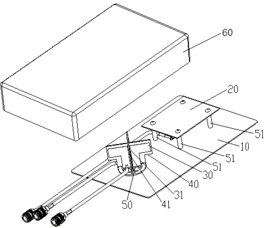
[0019] figure 1 is a structural schematic diagram of the MIMO antenna of the embodiment, from figure 1 It can be seen from the figure that an indoor MIMO antenna includes a radome 60, a radiator, a reflector 10, a fastening base 50, and a plastic support column 51. The radiator is arranged on the reflector 10, and the radome 60 is arranged on the radiator above and surround the radiator inside it, the radiator includes a metal patch 20, a first half-wave symmetric oscillator 30, a second half-wave symmetric oscillator 31, a first half-wave symmetric oscillator 30, a second half-wave symmetric The oscillators 31 are respectively printed on two mutually orthogonally crossed PCB boards, and the metal patch 20 and the orthogonally crossed PCB boards are both distributed on the longitudinal centerline of the reflector 10 .

[0020] Prefe...


PUM


Abstract

The invention discloses an indoor multiple input multiple output (MIMO) antenna which comprises an antenna cover, a radiator and a reflecting plate. The radiator is arranged on the reflecting plate, the antenna cover is arranged above the radiator and surrounds the radiator, the radiator comprises a metal patch and two half-wavelength dipoles, the half-wavelength dipoles are respectively printed on two printed circuit boards (PCBs) which are placed in mutual orthogonal cross mode, and the metal patch and the PCBs placed in orthogonal cross mode are evenly distributed on a longitudinal central line of the reflecting plate. The MIMO antenna can replace a wall-mounted antenna in an existing network directly, can support a double-channel device of time division-synchronization code division multiple access (TD-SCDMA), wireless local area network (WLAN) and long term evolution (LTE) frequency band, saves a large amount of resources for smooth transition of an indoor coverage system, and simultaneously provides more selection schemes for a future network integration scheme. The MIMO antenna is simple in structure, easy to assemble and debug, low in cost and favorable for mass production.

Description

technical field [0001] The invention relates to a mobile communication antenna, in particular to a MIMO antenna of a mobile communication indoor distribution system. Background technique [0002] With the rapid development of wireless communication technology, mobile users have higher and higher requirements for the capacity and quality of wireless communication. However, the current wireless channels have problems such as multipath attenuation, spectrum congestion, and noise interference, which greatly affect the data rate. improve. [0003] Multiple-input multiple-output ( MIMO ) antenna technology can double the quality and data rate of wireless communication without increasing the bandwidth and transmission power, especially the indoor stable and rich multi-path wireless environment is very conducive to the use of MIMO multiple Antenna technology. [0004] A broadband antenna that can satisfy multiple networks at the same time will undoubtedly meet the needs of operato...

Claims


Application Information

Patent Timeline
Patent Type & Authority Applications(China)
IPC IPC(8): H01Q1/36H01Q1/38H01Q19/10H01Q21/00
Inventor 邓遥林张慧萍石萌周柱
Owner WUHAN HONGXIN TELECOMM TECH CO LTD
Learn More