Novel cavity low-pass prototype power divider

A power divider and cavity technology, which is applied in the field of new cavity low-pass prototype power dividers, can solve problems such as power divider system mismatch, and achieve the effects of balanced power distribution, high power tolerance, and convenient installation and maintenance.

Inactive Publication Date: 2012-09-19
安徽科瑞达通信科技有限公司
View PDF8 Cites 0 Cited by
  • Summary
  • Abstract
  • Description
  • Claims
  • Application Information

AI Technical Summary

Problems solved by technology

Existing power splitters are prone to system mismatch

Method used


Image

  • Novel cavity low-pass prototype power divider
  • Novel cavity low-pass prototype power divider
  • Novel cavity low-pass prototype power divider

Examples


Embodiment Construction

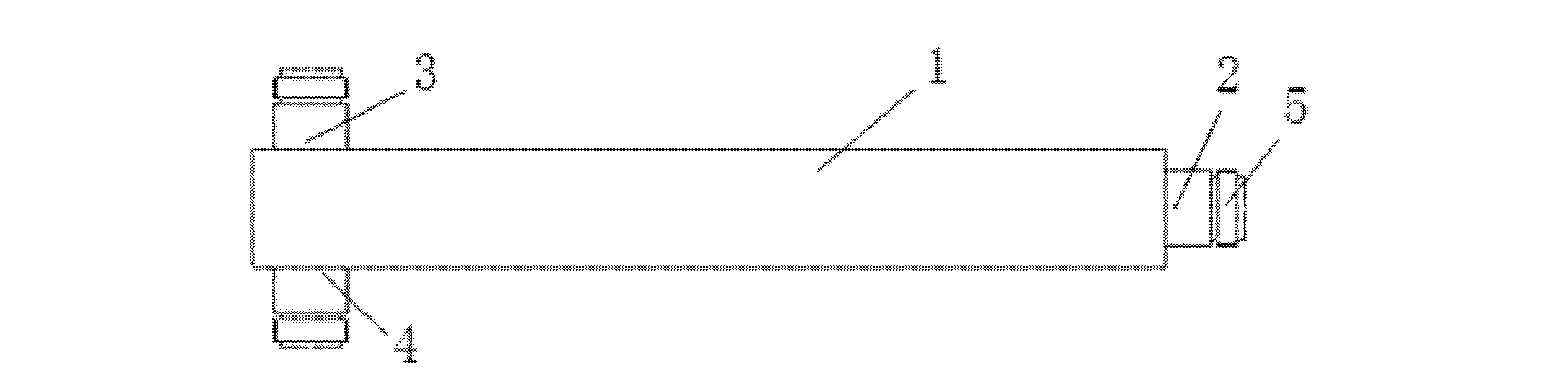
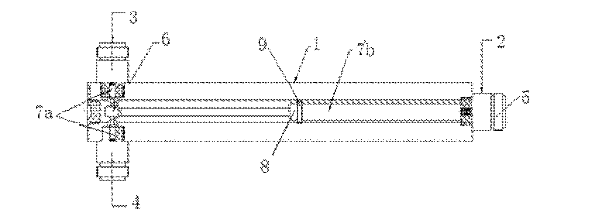
[0012] Such as figure 1 , 2 As shown, the new cavity low-pass prototype power splitter includes a shielding box 1, one end of the shielding box 1 is closed, the unclosed end of the shielding box 1 is used as the power input end 2, and the closed end of the shielding box 1 is A through hole is respectively opened on the upper and lower sides as the first and second power output terminals 3 and 4, and a joint 5 is respectively installed on the power input terminal 2 and the first and second power output terminals 3 and 4. A three-interface power distribution joint 6 is arranged between the two joints 5 of the two power output terminals 3 and 4, and the upper and lower interfaces of the power distribution joint 6 are respectively connected to the first and second joints through an impedance converter-7a. On the joint 5 of the two power output terminals 3 and 4, a plurality of impedance converters 2 7b are connected between the third interface of the power distribution joint 6 an...


PUM


Abstract

The invention discloses a novel cavity low-pass prototype power divider. The power divider comprises a shielding box, wherein one end of the shielding box is sealed, the other unsealed end of the shielding box serves as a power input end, through-holes are arranged on an upper surface of the sealed end of the shielding box and a lower surface of the sealed end of the shielding box respectively and serve as a first power output end and a second power output end, a joint is respectively installed at the power input end, the first power output end and the second power output end, a power distribution joint with three interfaces is arranged between the joint of the first power output end and the joint of the second power output end, the upper interface and the lower interface of the power distribution joint are connected with the joint of the first power output end and the joint of the second power output end respectively, a plurality of second impedance transformers are connected between the third interface of the power distribution joint and the joint of the power input end, and the plurality of second impedance transformers are connected with each other through impedance matching joints. The power divider has the advantages of being flexible, capable of eliminating system mismatching phenomena, convenient for establishment of communication networks and the like.

Description

technical field [0001] The invention mainly relates to the communication field, in particular to a novel cavity low-pass prototype power divider. Background technique [0002] The full name of the power divider is the power divider, and the English name is Power divider. It is a device that divides the energy of one input signal into two or more outputs with equal or unequal energy. It can also conversely synthesize the energy of multiple signals into one output. It can also be called a combiner. A certain degree of isolation should be guaranteed between the output ports of a power divider. The main technical parameters of the power splitter include power loss (including insertion loss, distribution loss and reflection loss), voltage standing wave ratio of each port, isolation between power distribution ports, power capacity and frequency bandwidth, etc. Existing power splitters are prone to system mismatch. Contents of the invention [0003] The purpose of the pres...

Claims


Application Information

Patent Timeline
Patent Type & Authority Applications(China)
IPC IPC(8): H01P5/16
Inventor 董后友肖本明刘海黄雪松
Owner 安徽科瑞达通信科技有限公司
Why Eureka
Try Eureka