Impact energy absorbing device of diaphragm bolt type tandem porous solid elements
A porous solid, energy-absorbing device technology, applied in the direction of shock absorbers, springs/shock absorbers, shock absorbers, etc., can solve the problems of limited energy absorption and easy instability of short and small honeycomb components, achieve simple and reasonable structure, avoid Unstable, easy-to-manufacture effects
- Summary
- Abstract
- Description
- Claims
- Application Information
AI Technical Summary
Problems solved by technology
Method used
Image

Examples
Embodiment 1
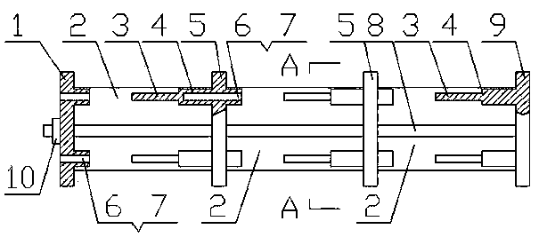
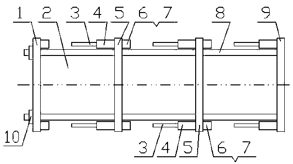
[0028] In this embodiment, there are three porous solid elements 2, two movable partitions 5, four guide rods 8, one sleeve end plate 1 and one bolt end plate 9, according to the attached figure 1 , 2 and 5 packs. Grooves matching the porous solid element 2 are provided on the contact surfaces of the sleeve end plate 1 , the movable partition plate 5 , the plug end plate 9 and the porous solid element 2 . The opening of the bolt sleeve 6 is provided with a sleeve bell mouth 7 for easy insertion of the bolt 3 . The pin end plate 9 is installed on the end facing the impact source, and is rigidly connected to one end of the guide rod 8; the sleeve end plate 1 is installed on the end away from the impact source, and is slidably connected to one end of the guide rod 8; 10 is mounted on one end of the guide rod 8 outside the sleeve end plate 1 . When the porous solid elements in series are compressed by external force, the porous solid element 2 and its movable partition 5 slide ...
Embodiment 2
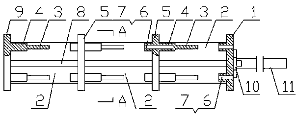
[0030] In this embodiment, there are three porous solid elements 2, two movable partitions 5, four guide rods 8, one sleeve end plate 1 and one bolt end plate 9, and one strike rod 11. According to attached image 3 , 4 and 5 packs. Grooves matching the porous solid element 2 are provided on the contact surfaces of the sleeve end plate 1 , the movable partition plate 5 , the plug end plate 9 and the porous solid element 2 . The opening of the bolt sleeve 6 is provided with a sleeve bell mouth 7 for easy insertion of the bolt 3 . The pin end plate 9 is installed at the end far away from the impact source, and is rigidly connected with one end of the guide rod 8; the sleeve end plate 1 is installed at the end facing the impact source, and is slidably connected with one end of the guide rod 8; 10 is installed on the end of the guide rod 8 outside the sleeve end plate 1, and the impact rod 11 is installed on the sleeve end plate 1. When the porous solid elements in series are ...
PUM
 Abstract
Description
Claims
Application Information
 - R&D
- Intellectual Property
- Life Sciences
- Materials
- Tech Scout
- Unparalleled Data Quality
- Higher Quality Content
- 60% Fewer Hallucinations
Browse by: Latest US Patents, China's latest patents, Technical Efficacy Thesaurus, Application Domain, Technology Topic, Popular Technical Reports.
© 2025 PatSnap. All rights reserved.Legal|Privacy policy|Modern Slavery Act Transparency Statement|Sitemap|About US| Contact US: help@patsnap.com