
Bionic manipulator

A kind of robotic and fuselage technology, which is used in the field of bionic robotics, can solve problems such as manual feeding, affecting production efficiency, etc., and achieve the effect of reducing labor intensity, convenient control, and simple structure

Inactive Publication Date: 2012-09-19
HENAN UNIV OF SCI & TECH
View PDF6 Cites 45 Cited by
  • Summary
  • Abstract
  • Description
  • Claims
  • Application Information

AI Technical Summary

Problems solved by technology

[0004] The purpose of the present invention is to provide a bionic manipulator to solve the technical problem in the prior art that manual loading and unloading is required during production, which affects production efficiency

Method used


Image

  • Bionic manipulator
  • Bionic manipulator
  • Bionic manipulator

Examples


Embodiment Construction

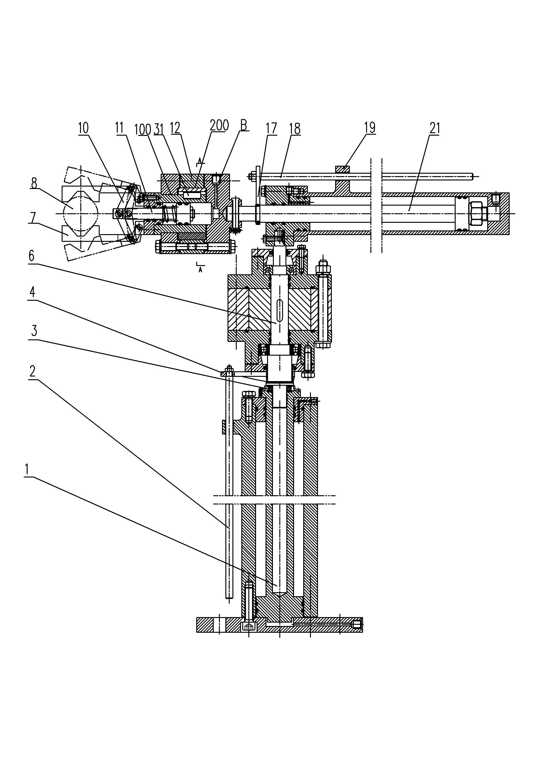
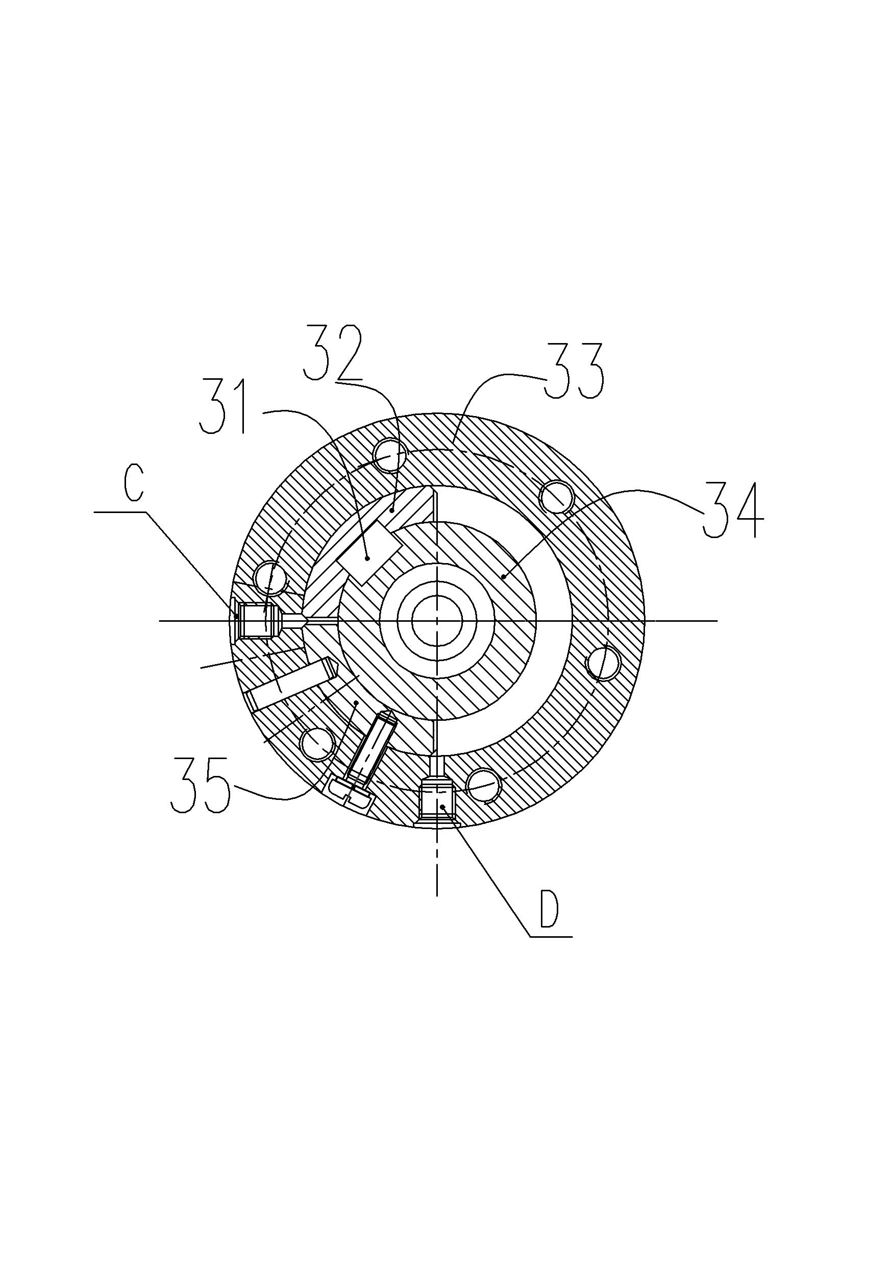
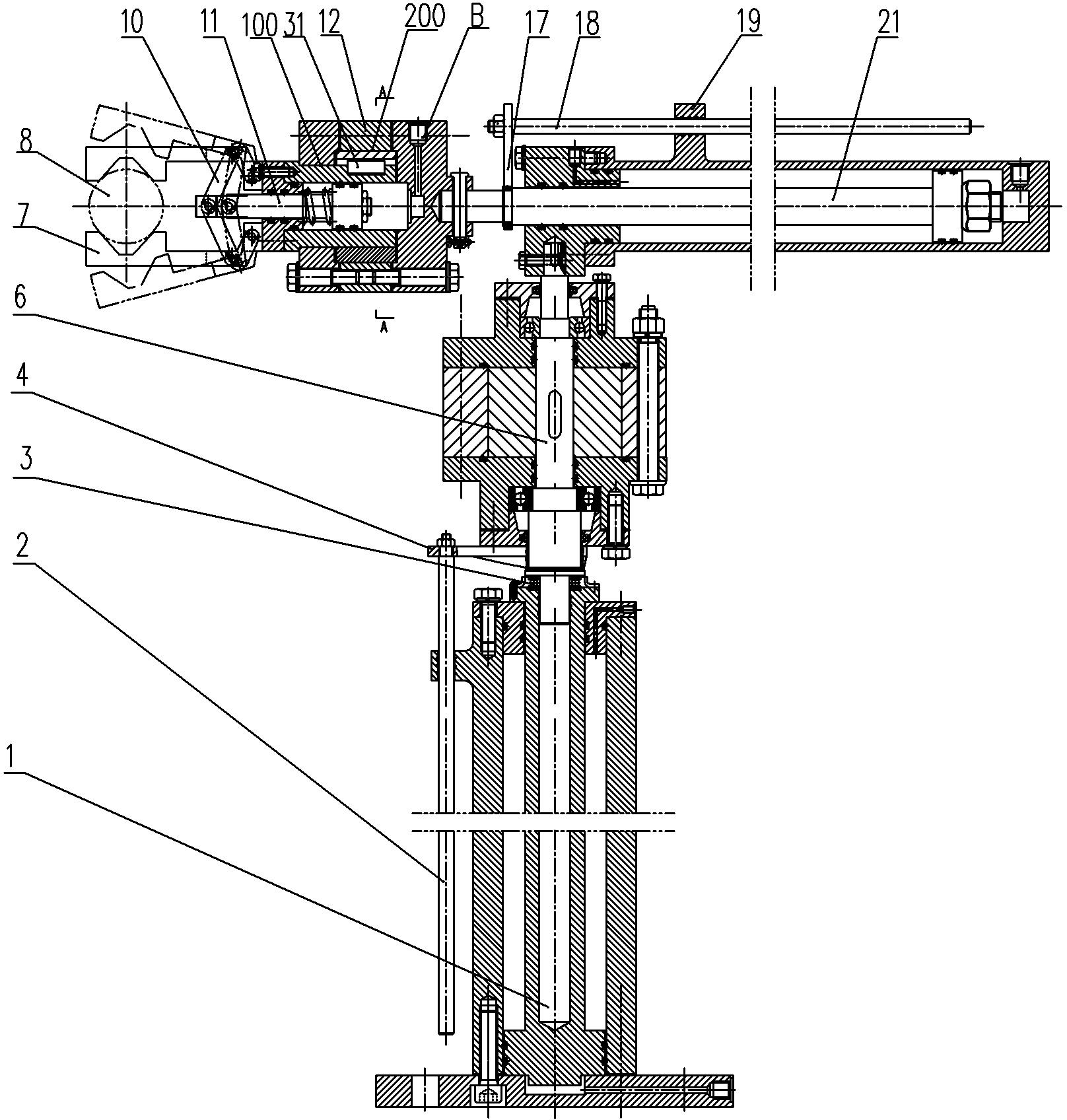
[0011] Such as figure 1 , figure 2 As shown, an embodiment of a bionic manipulator is shown. The bionic manipulator in this embodiment includes a body lifting cylinder 1 extending in a vertical direction. The output end of the body lifting cylinder 1 is fixedly provided with the center of the body lifting cylinder. The axis of the body revolving cylinder 6 is fixedly provided with an arm telescopic cylinder 21 extending in the horizontal direction on the output end of the body revolving cylinder 6, and the center of the arm telescopic cylinder is fixed on the output end of the arm telescopic cylinder 21 The axis-rotating wrist revolving cylinder 12 includes a fixed cylinder block fixed on the output end of the arm telescopic cylinder, and the fixed cylinder is provided with a revolving hole extending axially along the central axis of the arm telescopic cylinder, A drive telescopic cylinder 11 is installed in the revolving hole. The drive telescopic cylinder includes a drive cy...


PUM


Abstract

The invention discloses a bionic manipulator, which comprises a main body lifting cylinder, which extends along a vertical direction, wherein a main body rotating cylinder capable of rotating around a central axis of the main body lifting cylinder is fixedly arranged on the output end of the main body lifting cylinder, an arm telescopic cylinder, which extends along a horizontal direction, is fixedly arranged on the output end of the main body rotating cylinder, an artifice rotating cylinder, which rotates around the central axis of the arm telescopic cylinder, is fixedly arranged on the arm telescopic cylinder, and a paw part used for grabbing articles is arranged on a rotating output part on the artifice rotating cylinder. When used, materials are grabbed by the paw part firstly, and then the paw part is moved and adjusted to a proper position through a telescopic action of the arm telescopic cylinder, a rotating action of the main body rotating cylinder and a lifting action of the main body lifting cylinder according to actual requirements, when the paw is moved in place, the materials are put down by the paw part, so that the materials can be conveyed without manual work.

Description

Technical field [0001] The invention belongs to the technical field of robots, and specifically relates to a bionic manipulator suitable for high-risk and heavy physical labor occasions such as inflammable and explosive in industrial sites. Background technique [0002] Modern industrial robots are similar in structure to human arms and remote manipulators, and their control principles are based on the concepts of numerical control and remote control. Modern industrial robots are regarded as "numerical control operating arms", in which the main arm directly operated by the operator is replaced by a computer numerical control device. The industrial robot is composed of a manipulator (mechanical body), a controller, a servo drive system and a detection sensor device. It is a kind of mechatronics automation that simulates human operation, automatic control, repeatable programming, and can complete various tasks in three-dimensional space. Production equipment. It is especially sui...

Claims


Application Information

Patent Timeline
Patent Type & Authority Applications(China)
IPC IPC(8): B25J9/08
Inventor 张伏付三玲毛鹏军邱兆美王俊徐锐良薛坤鹏杨乐峰王海源白延鹏
Owner HENAN UNIV OF SCI & TECH
Learn More