
Drawing machine

A technology of drawing machine and frame, applied in the field of drawing machine, can solve the problems of poor stability of drawing operation and achieve the effect of smooth drawing

Inactive Publication Date: 2012-09-19
苏州中信科技股份有限公司
View PDF4 Cites 8 Cited by
  • Summary
  • Abstract
  • Description
  • Claims
  • Application Information

AI Technical Summary

Problems solved by technology

[0003]The existing drawing machine uses a single-sided cam to drive the drawing trolley to move, relying on the hard contact between the roller of the drawing trolley and the curved surface of the single-sided cam to produce the drawing force to realize the pulling of the object to be pulled, so the stability of the pulling operation is poor

Method used


Image

  • Drawing machine
  • Drawing machine
  • Drawing machine

Examples


Embodiment Construction

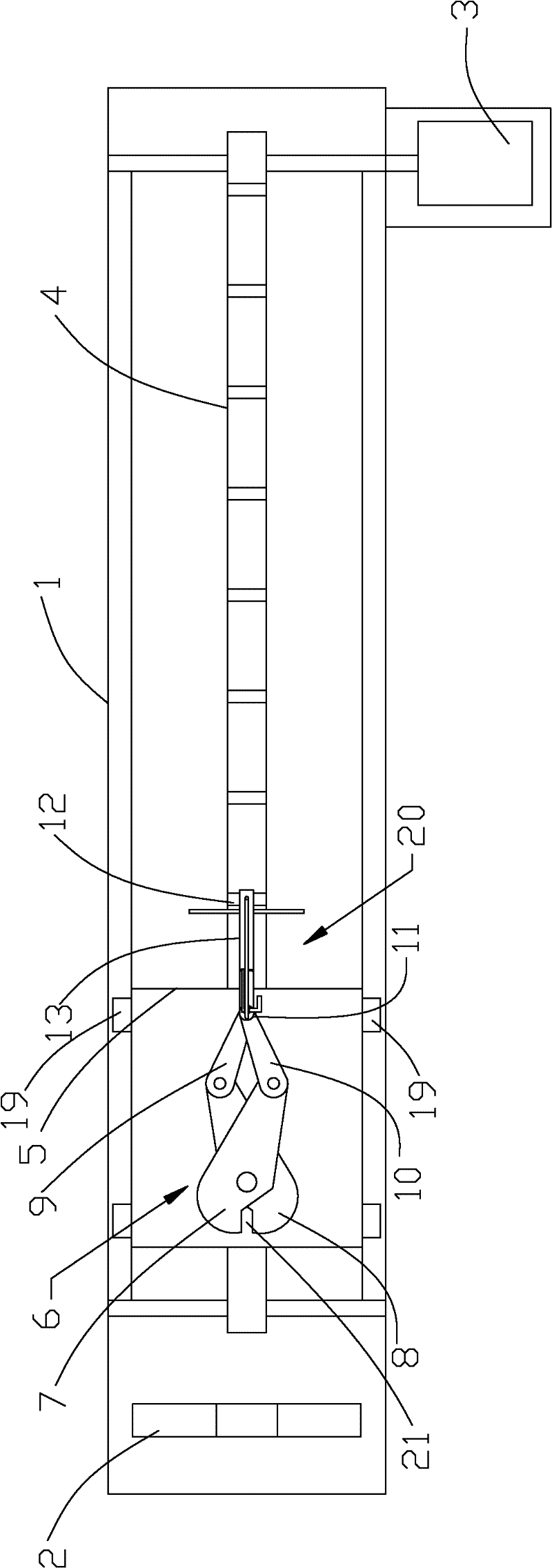
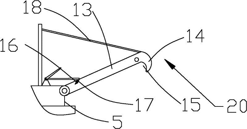
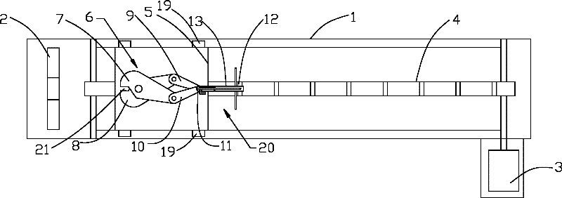
[0014] exist figure 1 and 2 Among them, a drawing machine includes a machine base 1, a mold mounting seat 2 arranged on the machine base 1 for installing a mould, a driving sprocket and a driven sprocket arranged on the machine base 1, and a transmission connection driving sprocket and the drive chain 4 of the driven sprocket, the clamp seat 5 arranged on the machine base 1 to move along the moving direction of the drive chain 4, and the clamp seat 5 arranged on the clamp seat 5 for clamping the drawn piece passing through the mold. The clamp 6 at one end of the object, the connection mechanism 20 used to connect the clamp seat 5 to the transmission chain 4, the driving sprocket is driven to rotate by the motor 3, and is driven by the driven sprocket with the chain 4, and the connection mechanism 20 The chain 4 moves together with the clamp seat 5, and the clamp 6 includes a first clamp block 7 and a second clamp block 8 which are arranged to cross and rotate, and an end por...


PUM


Abstract

The invention discloses a drawing machine. A quadrilateral connecting rod structure is composed of a first clamp block, a second clamp block, a first connecting rod and a second connecting rod. The quadrilateral structure is not stable, so, when drawing, one end of things to be drawn passes through a mould and enters into a clamping opening aperture, and is clamped by the first clamp block and the second clamp block; and clamps are driven to move toward a direction away from the mould by a rotating shaft which is connected with a clamper and which is arranged between the first connecting rod and the second connecting rod, when the clamper is taken to move far away from the mould by a chain of a connecting mechanism. Due to the presence of drawing resistance, the first connecting rod and the second connecting rod are close up, the first clamp block and the second clamp block are also close up, and the clamping opening aperture is reduced, when the quadrilateral connecting rod structure begins to co-move, so that things to be drawn can be clamped more tightly, move toward the direction away from the mould along with the chain, and be drawn to appropriate sizes through the mould. Smoothly drawing of the mould is realized through transmission chains by the drawing machine.

Description

[0001] technical field [0002] The invention relates to a drawing machine. Background technique [0003] The existing drawing machine uses a single-sided cam to drive the drawing trolley to move, relying on the drawing force generated by the hard contact between the roller of the drawing trolley and the curved surface of the single-sided cam to realize the drawing of the object to be drawn. The stability of operation is poor. Contents of the invention [0004] The purpose of the present invention is to provide a drawing machine which can realize smooth drawing through the movement of the transmission chain with the holder and the clamp. [0005] In order to achieve the above object, the technical solution adopted by the present invention is: a drawing machine, including a machine base, a mold mounting seat set on the machine base for installing a mold, and a driving sprocket set on the machine base and the driven sprocket, the transmission chain connecting the driving s...

Claims


Application Information

Patent Timeline
IPC IPC(8): B21C1/00
Inventor 邱九根
Owner 苏州中信科技股份有限公司
Learn More