
Fire scene rescue device

A fire field and control unit technology, applied in fire rescue, life-saving equipment, respiratory protection containers, etc., to achieve the effect of ensuring safety

Inactive Publication Date: 2012-09-19
JINGAN DISTRICT JUVENILE ACTIVITY CENT
View PDF0 Cites 11 Cited by
  • Summary
  • Abstract
  • Description
  • Claims
  • Application Information

AI Technical Summary

Problems solved by technology

[0002] At present, there is a lack of a device for assisting firefighters in rescue work

Method used


Image

  • Fire scene rescue device
  • Fire scene rescue device

Examples


Embodiment Construction

[0012] The present invention will be further described below in conjunction with specific examples.

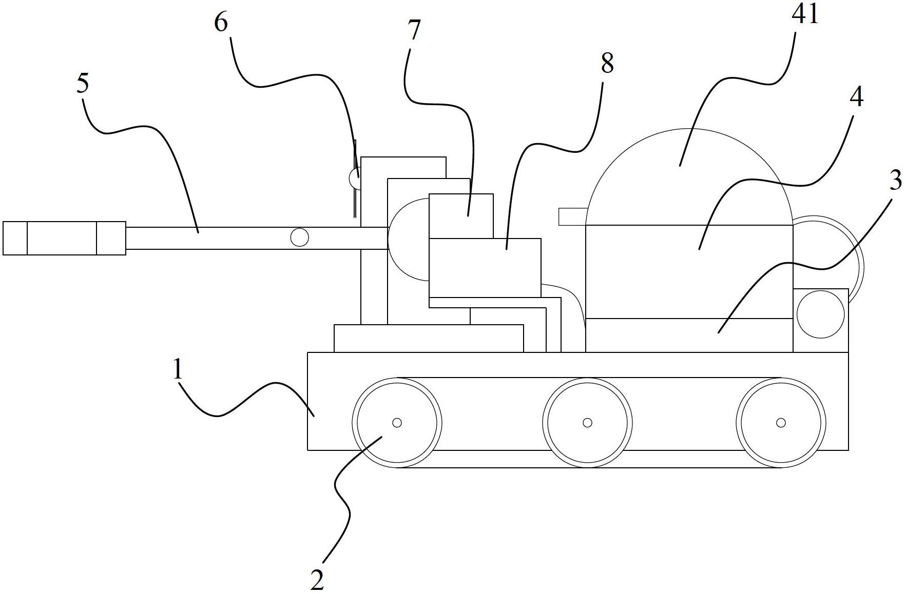
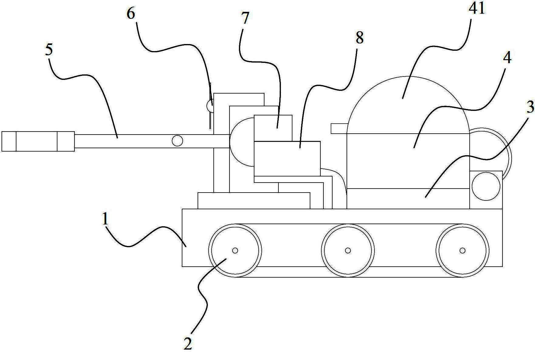
[0013] see figure 1 , a fire rescue device of the present invention, comprising a base 1, a control unit 3, a camera 7 and a mechanical arm 5, the mechanical arm 5 is connected to the base 1 through a first motor, the first motor and the control unit 3 Electrically connected, the control unit 3 and the camera 7 communicate with the remote control center, and also include a safety cabin 4 and a plurality of track wheels 2, the track wheels 2 are fixed on both sides of the base 1 through a second motor drive, and the track wheels 2 realize The robot can easily go up and down the stairs; the second motor is electrically connected with the control unit 3, and the safety cabin 4 is fixed on the base 1.

[0014] Camera 7 provides fire scene real-time information to rescuers.

[0015] The top of the safety cabin 4 is provided with a hatch 41 , the hatch 41 is openably sealed and co...


PUM


Abstract

The invention discloses a fire scene rescue device. The fire scene rescue device comprises a base, a control unit, a camera, a mechanical arm, a safety cabin and a plurality of crawler wheels, wherein the mechanical arm is connected with the base through a first motor in a transmission mode; the first motor is electrically connected with the control unit; the control unit and the camera are in communication connection with a remote control center; the crawler wheels are fixed on two sides of the base through a second motor which is electrically connected with the control unit; and the safety cabin is fixed on the base. Due to the adoption of the fire scene rescue device, a robot can walk upstairs and downstairs easily and can rescue people effectively, and the fire scene rescue device has the advantages of high stability and safety.

Description

technical field [0001] The invention relates to a rescue device, in particular to a fire rescue device. Background technique [0002] At present, there is a lack of a device for assisting firefighters to carry out rescue work. Contents of the invention [0003] The purpose of the present invention is to overcome the defects of the prior art and provide a fire rescue device. A robot that can easily go up and down stairs and can effectively carry out rescue work is realized, which has the advantages of strong stability and high safety. [0004] The technical scheme for realizing the above-mentioned purpose is: [0005] A fire rescue device of the present invention includes a base, a control unit, a camera and a mechanical arm, the mechanical arm is connected to the base through a first motor, and the first motor is connected to the control unit Electrically connected, the control unit and the camera are connected in communication with the remote control center. It is char...

Claims


Application Information

Patent Timeline
Patent Type & Authority Applications(China)
IPC IPC(8): A62B31/00A62C3/00
Inventor 黄颖颖赵今阳潘心一
Owner JINGAN DISTRICT JUVENILE ACTIVITY CENT
Learn More