


Quick Research
Generate reliable direction feasibility study reports for your R&D in just a few steps.

Technical Q&A
Discover and master advanced knowledge NOW. Basics, ideas, possibilities, all at once.

Find Solutions
As an expert in R&D theories, this can generate solutions to your technical problems instantly.

Evaluate Feasibility
Analyze your overall solution with one click, know your potential R&D risks in advance.

Monitor Landscape
Get weekly tech updates, stay abreast of the latest tech innovations and key insights.
Measurement device and sensor placement method
A measurement device and sensor technology, applied in sensors, diagnostic recording/measurement, medical science, etc., can solve problems such as inability to perform continuous measurement and heavy burden on patients
- Summary
- Abstract
- Description
- Claims
- Application Information
AI Technical Summary
Problems solved by technology
Method used
Image

Examples
Embodiment approach 1
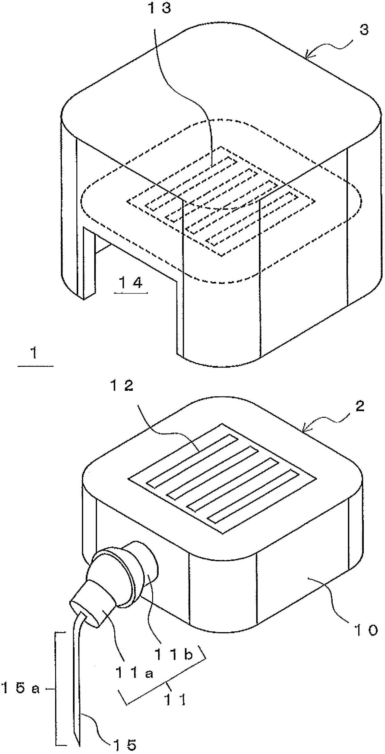
[0053] Below, refer to Figure 1 ~ Figure 3 The measurement device and sensor placement method in Embodiment 1 of the present invention will be described. First, use figure 1 The configurations of the measurement device 1 and the sensor unit 2 in the first embodiment will be described. figure 1 It is a perspective view showing the configuration of the measurement device and the sensor unit in Embodiment 1 of the present invention.
[0054] figure 1 The shown measurement device 1 is a device for measuring numerical information on substances contained in body fluids in the body. Such as figure 1 As shown, the measurement device 1 includes a sensor unit 2 and a control unit 3 . In addition, examples of body fluids in the body include interstitial fluid, blood, plasma, and the like. Also, "in vivo" in this specification includes "subcutaneous" under the surface of the skin.
[0055] The sensor unit 2 includes a base 10 , a variable mechanism 11 and a sensor 15 . Among ...
Embodiment approach 2
[0088] Below, refer to Figure 6 and Figure 7 The measurement device and sensor placement method in Embodiment 2 of the present invention will be described. First, the first example in Embodiment 2 will be described. Figure 6 It is a perspective view showing the structure of the first example of the sensor unit in Embodiment 2 of the present invention.
[0089] Such as Figure 6 As shown, the sensor unit 20 in the first example of the second embodiment is different from that in the first embodiment in terms of the structure of the variable mechanism 21 figure 1 The sensor unit 2 shown is different. The variable mechanism 21 includes: a rotating member (rotating shaft) 22 formed in a shaft shape; and a holding member 23 that holds the rotating member 22 rotatably.
[0090] The holding member 23 includes a plate-shaped portion 23c and a pair of portions 23a and 23b protruding perpendicularly from the plate-shaped portion 23c. And, the holding member 23 holds both ends o...
Embodiment approach 3
[0101] Below, refer to Figure 8 ~ Figure 10 The measurement device, the sensor unit, and the sensor placement method using these measurement devices and sensor units in Embodiment 3 of the present invention will be described. First, use Figure 8 The configuration of the sensor unit 30 in Embodiment 3 will be described. Figure 8 It is a perspective view showing the structure of the sensor unit in Embodiment 3 of the present invention, Figure 8 (a) shows the state after the sensor is removed, Figure 8 (b) shows the state where the sensor is attached.
[0102] Such as Figure 8 (a) and Figure 8 As shown in (b), the sensor unit 30 includes a variable mechanism 31 . and the variable mechanism 21 shown in the first example of Embodiment 2 (refer to Figure 6 ) Similarly, the variable mechanism 31 includes a rotating member 32 and a holding member 33 that holds the rotating member 32 rotatably.
[0103] with retaining part 23 (refer to Figure 7 ) Similarly, the holdin...
PUM
 Abstract
Description
Claims
Application Information
 - R&D Engineer
- R&D Manager
- IP Professional
- Industry Leading Data Capabilities
- Powerful AI technology
- Patent DNA Extraction
Browse by: Latest US Patents, China's latest patents, Technical Efficacy Thesaurus, Application Domain, Technology Topic, Popular Technical Reports.
© 2024 PatSnap. All rights reserved.Legal|Privacy policy|Modern Slavery Act Transparency Statement|Sitemap|About US| Contact US: help@patsnap.com