
Alternative-optimization and rate-maximization multi-point cooperation wave beam forming method

A rate and transmit beam technology, applied in the direction of diversity/multi-antenna system, space transmit diversity, advanced technology, etc.

Inactive Publication Date: 2012-09-12
SOUTHEAST UNIV +1
View PDF3 Cites 5 Cited by
  • Summary
  • Abstract
  • Description
  • Claims
  • Application Information

AI Technical Summary

Problems solved by technology

At present, the design of multi-point cooperative beamforming and power allocation methods mainly focuses on the problem of how to design beam vectors and power allocation between cooperative base stations under the total power constraints between cooperative base stations. There are relatively few literatures that study the power constraints of each base station. Next, how to design the beam vector and power allocation between cooperative base stations

Method used


Image

  • Alternative-optimization and rate-maximization multi-point cooperation wave beam forming method
  • Alternative-optimization and rate-maximization multi-point cooperation wave beam forming method
  • Alternative-optimization and rate-maximization multi-point cooperation wave beam forming method

Examples


Embodiment Construction

[0042] Specific theoretical basis description:

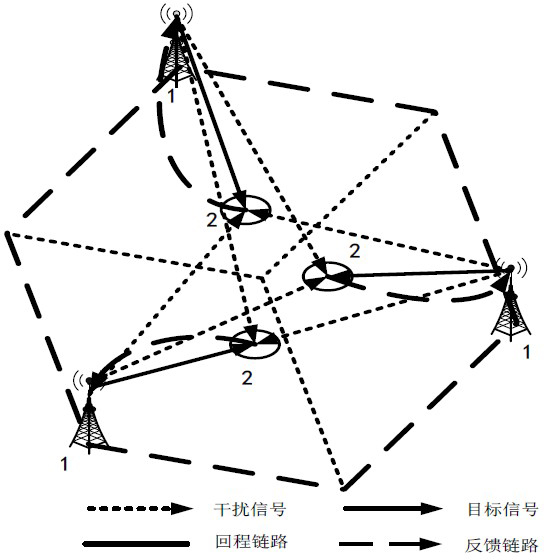
[0043] The present invention aims at the multi-input single-output multi-point coordinated downlink system with single base station power constraints, and optimizes the solution system and speed maximization as the optimization goals, namely:

[0044] max { w b , p b } b = 1 K Σ u = 1 K R u - - - ( 1 )

[0045] s . t . | | w b ...


PUM


Abstract

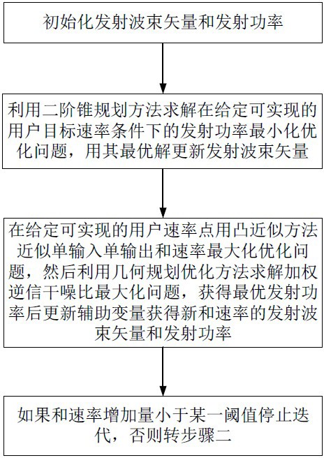
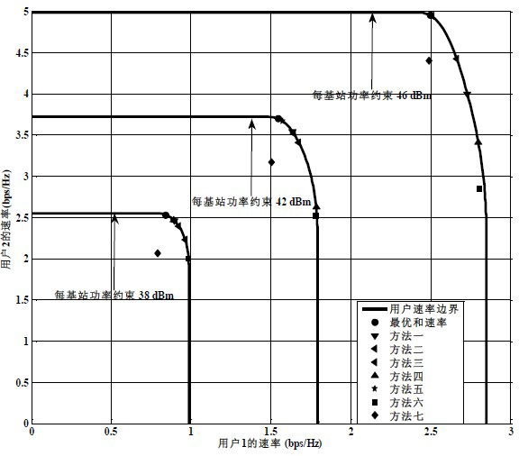
The invention discloses a single base station power constraint and rate maximization multipoint cooperation wave beam forming and power distribution method. The method comprises the following steps: firstly, converting sum rate maximization problem into an emission power minimization problem satisfying a minimum rate requirement; secondly, using a second-order cone programming optimization method to solve the emission power minimization problem so as to obtain an emission wave beam vector and emission power; then, taking the obtained wave beam vector as a constant, converting the sum rate maximization optimization problem into the sum rate maximization optimization problem of a single-input single-output communication network, and using a convex approximation method and a geometric programming optimization method to solve the sum rate maximization optimization problem so as to obtain the emission power of the sum rate maximization when the emission wave beam vector is given. Compared to the current sum rate maximization multipoint cooperation wave beam forming method, by using the method of the invention, calculating complexity is low and the sum rate obtained through the method of the invention approximates the optimal sum rate searched by an exhaustive method.

Description

technical field [0001] The invention belongs to the technical field of wireless communication, and in particular relates to a method for sum rate maximization multi-point cooperative beamforming and power distribution under the power constraint of a single base station. Background technique [0002] In order to improve the utilization efficiency of the spectrum, the cellular mobile communication system generally adopts the spectrum multiplexing method with a spectrum reuse factor of 1 to construct the communication network, which not only realizes the increase of the spectrum utilization efficiency, but also alleviates the pressure of the cell planning and the placement of the base station nodes. However, the cellular mobile network constructed by this method produces serious inter-cell interference, especially the impact of co-channel interference on cell edge users is more serious, which leads to a serious impact on the throughput performance of the cellular mobile communic...

Claims


Application Information

Patent Timeline
IPC IPC(8): H04B7/06H04W16/28
CPCY02D30/70
Inventor 黄永明何世文杨绿溪金石姜蕾雷鸣
Owner SOUTHEAST UNIV
Learn More