
Seal for an adjustment device for a supercharging device

一种调节装置、增压装置的技术,应用在燃气轮机装置、发动机元件、机器/发动机等方向,能够解决轴和调节装置故障概率升高、密封件安装繁琐、增加时间和成本等问题,达到改善密封效果、快速安装或布置、防止涡轮逸出的效果

Inactive Publication Date: 2012-09-05
IHI CHARGING SYST INT
View PDF3 Cites 5 Cited by
  • Summary
  • Abstract
  • Description
  • Claims
  • Application Information

AI Technical Summary

Problems solved by technology

[0003] The disadvantage of the sealing of the adjusting shaft arrangement by the seal arranged between the adjusting shaft and the bushing is that the adjusting shaft has a groove corresponding to the sealing, which means that the adjusting shaft is weakened.
This presents a problem in case the adjusting bearing is exposed to high temperatures, i.e. an increased probability of failure of the shaft and the adjusting device due to the weakening of the shaft due to the slots
Furthermore, the seals are very cumbersome to install, thereby increasing time and cost
[0004] Another problem is that a seal cannot be achieved between the bushing and the housing containing it, which leads to undesired gas leakage

Method used


Image

  • Seal for an adjustment device for a supercharging device
  • Seal for an adjustment device for a supercharging device
  • Seal for an adjustment device for a supercharging device

Examples


Embodiment Construction

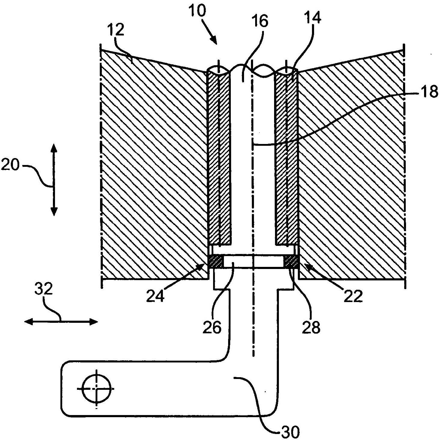
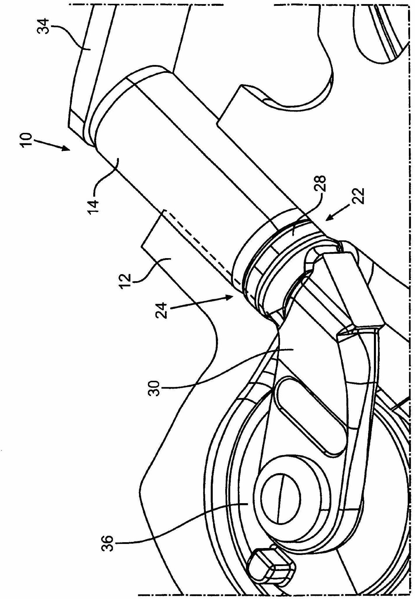
[0024] figure 1 Shown is a regulating device 10 for a charging device in the form of an exhaust-gas turbocharger with a housing 12, wherein the housing 12 is designed as a turbine housing for accommodating the exhaust-gas turbocharger. Turbo turbine wheel.

[0025] The adjusting device 10 comprises a bearing element in the form of a bushing 14 in which an adjusting shaft 16 of the adjusting device 10 is accommodated. as available from figure 1 It can be seen that the adjusting shaft 16 is mounted in the housing 12 so as to be rotatable about an axis of rotation 18 by means of a bushing 14 .

[0026] The adjusting shaft 16 has a section 22 protruding beyond the bushing 14 in the axial direction of the adjusting shaft 16 indicated by the direction arrow 20 , in which section a collar 24 of the adjusting shaft 16 is arranged.

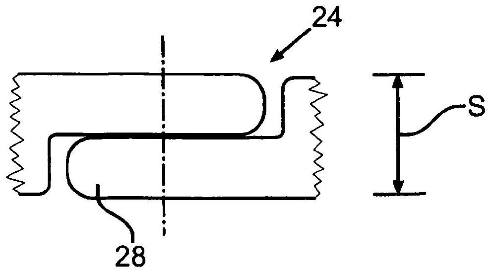
[0027] The collar 24 also has a groove 26 in which a corresponding sealing element in the form of a sealing ring 28 is arranged, so that the sealing ri...


PUM


Abstract

The invention relates to an adjustment device (10) for a supercharging device, in particular an exhaust gas turbocharger, comprising a bearing element (14), in particular a bushing (14), in which an adjustment shaft (16) is accommodated at least in some sections and by means of which the adjustment shaft (16) can be supported in a housing (12) of the supercharging device, wherein at least one sealing element (28) is arranged on the adjustment shaft (16) in a section (22) of the adjustment shaft (16) that protrudes beyond the bearing element (14) in the axial direction (20).

Description

technical field [0001] The invention relates to a control device for a charging device, in particular for an exhaust-gas turbocharger, of the type specified in the preamble of claim 1 . Background technique [0002] Conventional adjustment devices are well known. DE 202005008606U1 discloses an adjusting shaft arrangement of a turbocharger with variable turbine geometry or with exhaust valves, which comprises an adjusting shaft with a fixed section. Furthermore, the adjusting shaft arrangement comprises a rod connected to the adjusting shaft via the fastening section and a bushing arranged on the base body of the adjusting shaft. In addition, a seal is provided which is arranged in the region between the bushing of the basic body and the adjusting shaft, wherein the basic body of the adjusting shaft has a stepped outer contour and the bushing has a shape complementary to that of the basic body. inner contour of . [0003] The sealing of the adjusting shaft arrangement by t...

Claims


Application Information

Patent Timeline
Patent Type & Authority Applications(China)
IPC IPC(8): F02C6/12
CPCF01D17/20F02C6/12F05D2240/55
Inventor J·S·德利茨
Owner IHI CHARGING SYST INT
Learn More