
Switching power supplier provided with frequency conversion device

A technology of power supply and frequency conversion device, which is applied in the conversion device of output power, conversion of DC power input to DC power output, instruments, etc., can solve problems such as large loss, low output voltage, and reduced output power.

Inactive Publication Date: 2012-09-05
ASIAN POWER DEVICES
View PDF5 Cites 2 Cited by
  • Summary
  • Abstract
  • Description
  • Claims
  • Application Information

AI Technical Summary

Problems solved by technology

[0004] The main purpose of the present invention is to provide a control circuit that can adjust the switching frequency of a pulse width modulation control device (hereinafter referred to as PWM control device) to solve the problem of excessive loss of conventional switching power supplies at light loads, and to improve When it is in the peak load (peak lord), the output voltage drops, causing the problem of output power reduction

Method used


Image

  • Switching power supplier provided with frequency conversion device
  • Switching power supplier provided with frequency conversion device
  • Switching power supplier provided with frequency conversion device

Examples


Embodiment Construction

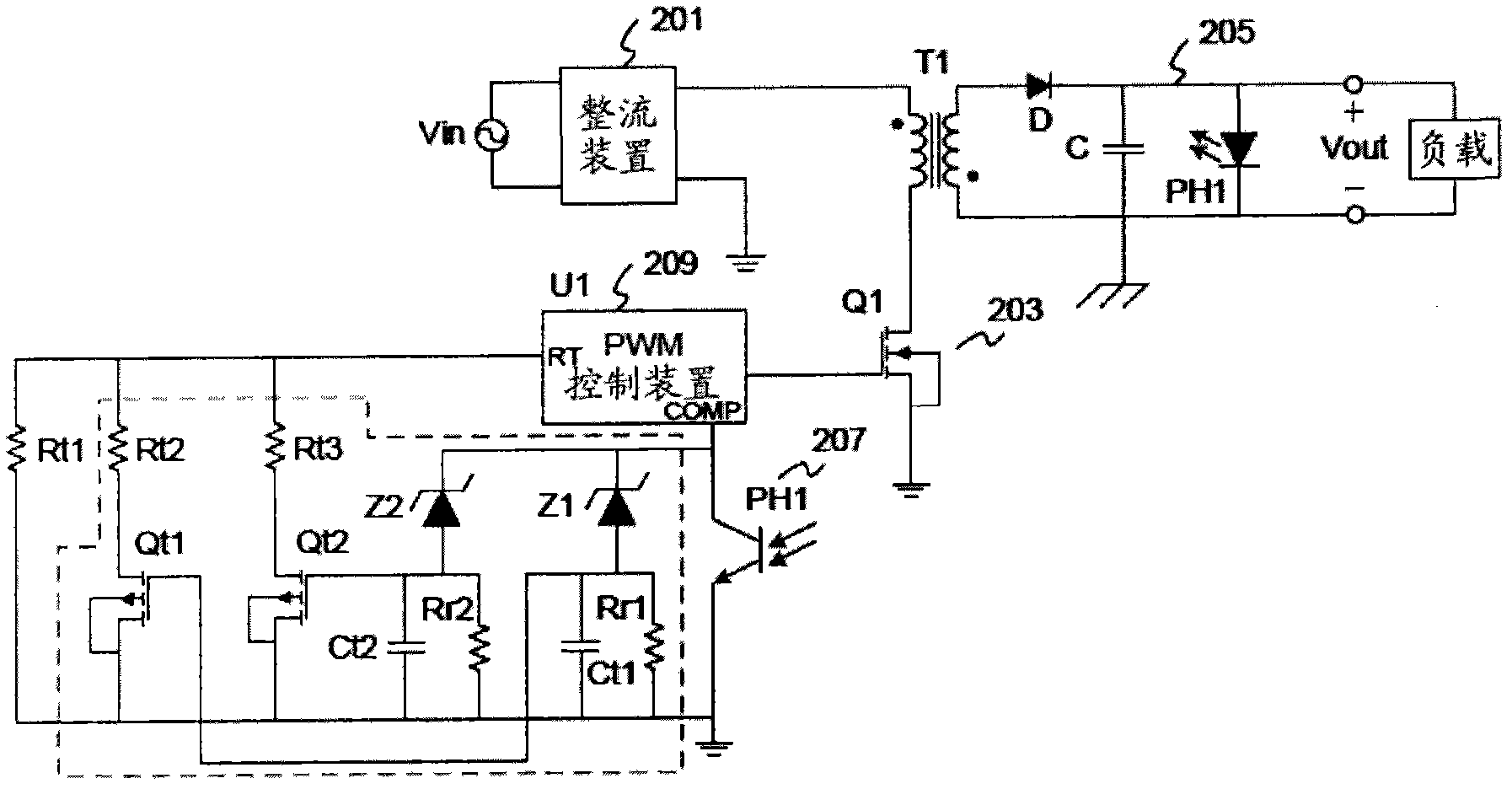
[0027] The purpose of the present invention is to achieve a switching frequency up and down by adjusting the switching frequency of the pulse width modulation control device (hereinafter referred to as the PWM control device) 209, so that the switching power supply can be reduced in frequency when the load is light. Energy saving, when the load is overloaded, the frequency can be increased to increase the power output to stabilize the load.

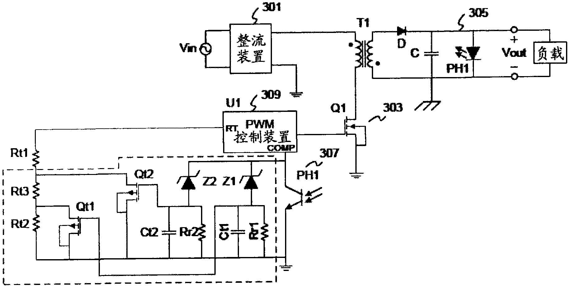
[0028] like figure 2 Shown is a circuit diagram of an embodiment of a switching power supply with a variable frequency device of the present invention. figure 2 The medium switching power supply is composed of a rectifier 201, a transformer (transformer) T1, an output circuit 205, a switching device 203, a pulse width modulation control device 209, a feedback circuit 207 and a frequency conversion modulation device. Wherein the frequency conversion modulation device is respectively connected to the feedback circuit 207 and the PWM cont...


PUM


Abstract

The invention discloses a switching power supplier provided with a frequency conversion device, comprising a rectifying device, a voltage transformation device, an output circuit, a switch device, a pulse width modulation control device, a feedback circuit, a pulse width modulation control device, and a frequency conversion modulation device used for modulating switch frequency of the pulse width modulation control device. The frequency conversion modulation device comprises a first frequency modulation resistance connected with the pulse width modulation control device, a first reference voltage circuit and a second reference voltage circuit respectively connected with the pulse width modulation control device, a second frequency modulation resistance in a bridge joint between the pulse width modulation control device and a first by-pass switch, and a third frequency modulation resistance in a bridge joint between the pulse width modulation control device and a second by-pass switch, wherein the first by-pass switch is connected with the first reference voltage circuit, and the second by-pass switch is connected with the second reference voltage circuit.

Description

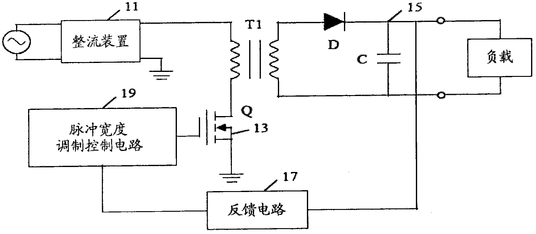
technical field [0001] The invention relates to a power supply device, especially a power supply device with a frequency conversion device. Background technique [0002] like figure 1 In the switching power supply shown, the rectifying device 11 receives an input AC voltage, rectifies it into DC and outputs it to the input terminal of the transformer T1. The primary side winding of the transformer T1 receives the rectified direct current, and stores energy in the primary side winding when the switching device 13 is turned on, and transmits the energy stored in the primary side winding of the transformer T1 to the secondary side winding when the switching device 13 is turned off . The output circuit 15 is arranged between the secondary winding and the load, and is used to output the DC voltage to the load. The feedback circuit 17 receives the output of the switching power supply, and transmits the output change of the power supply to the pulse width modulation (Pulse Width...

Claims


Application Information

Patent Timeline
Patent Type & Authority Applications(China)
IPC IPC(8): H02M3/335H02M1/32
Inventor 庄乙雄吴芝雅
Owner ASIAN POWER DEVICES
Learn More