Laundry dryer with fluff filter cleaning

A technology for cleaning devices and dryers, applied in washing devices, household dryers, household appliances, etc., can solve problems such as regular replacement, and achieve the effect of compact design

Inactive Publication Date: 2012-09-05
V ZUG
View PDF8 Cites 9 Cited by
  • Summary
  • Abstract
  • Description
  • Claims
  • Application Information

AI Technical Summary

Problems solved by technology

[0003] In most conventional installations the fluff filte

Method used


Image

  • Laundry dryer with fluff filter cleaning
  • Laundry dryer with fluff filter cleaning
  • Laundry dryer with fluff filter cleaning

Examples


Example Embodiment

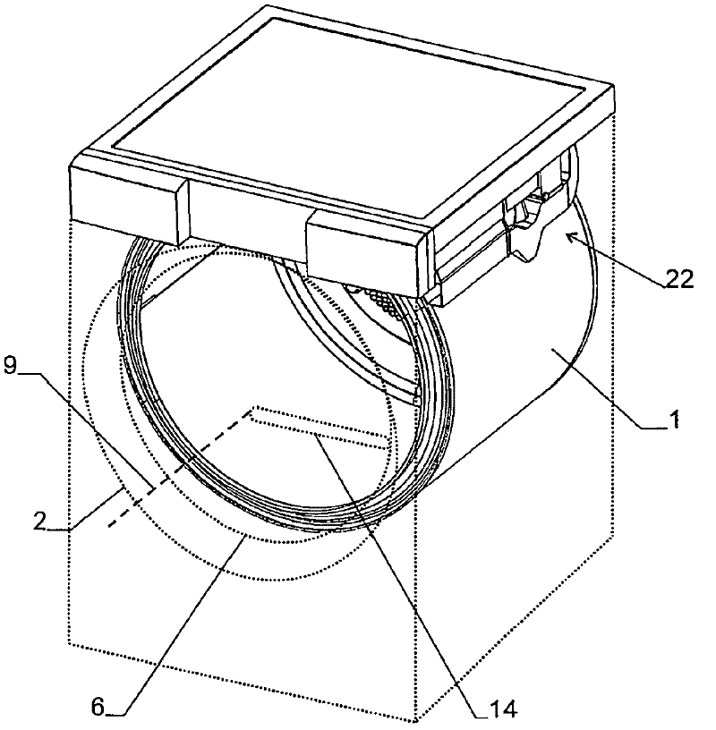
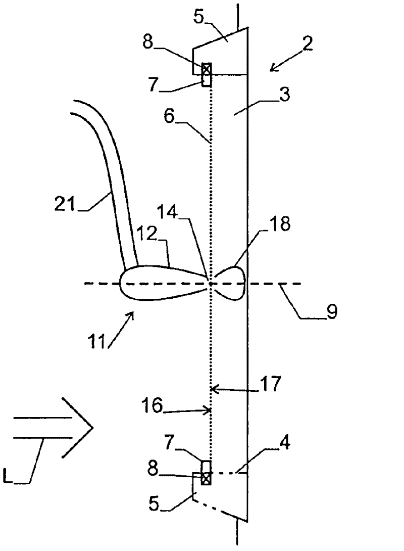
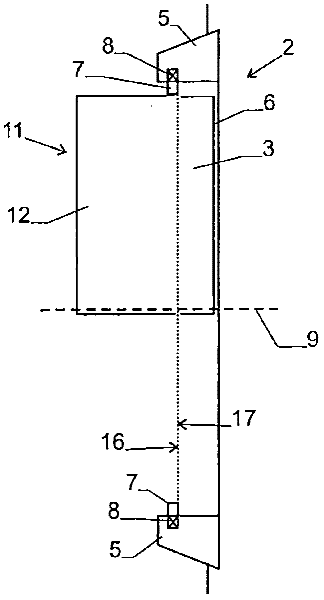
[0023] figure 1 , figure 2 with image 3 The embodiment of the laundry dryer shown in FIG. 1 includes a drum 1 for receiving laundry to be dried and a door 2 through which the inside of the drum 1 can be accessed. The device also includes a device (not shown) for generating a processing air flow L in the drum 1. The process air flow enters, for example, through the rear wall of the drum 1 and flows through the drum 1 in a substantially horizontal direction. It then enters the cavity 3 in the door 2 and exits the cavity 3 through an opening 4 in the frame 5 of the door. From here, the air enters the dehumidification and heating device located in the base of the laundry dryer and then returns to the drum 1 by means of a blower (not shown). As from figure 2 with image 3 As best seen in the above, the fluff filter 6 is arranged in the door 2. The fluff filter 6 is a fine mesh, which has an opening in the range of 0.05 mm-0.15 mm, specifically 0.13 mm, which is used to maintain...


PUM


Abstract

In order to clean the fluff filter (6) of a laundry dryer, a suction nozzle (11) is provided. The fluff filter (6) can be rotated relatively to the suction nozzle (11) such that the suction nozzle (11) covers the whole fluff filter (6). The air from the suction nozzle (11) is fed to a suction device (22), which separates the fluff from the air and feeds the fluff to a fluff container (24). In this manner the fluff filter (6) can be cleaned efficiently.

Description

technical field [0001] The invention relates to a laundry dryer with a fluff filter and a cleaning device for cleaning the fluff filter. Background technique [0002] The laundry dryer should be provided with at least one fluff filter for removing fluff from the process air. Such fluff filters are arranged, for example, on the door of the device. [0003] In most conventional installations, the fluff filter has to be cleaned by hand or has to be replaced periodically. EP 2 226 421 describes a laundry dryer in which a cleaning device is provided for automatically cleaning the fluff filter. The cleaning device consists of a wiper that slides over the lint filter. Contents of the invention [0004] The object of the invention is to design a cleaning device for a fluff filter in such a way that a good cleaning action can be achieved. [0005] This object is met by a laundry dryer as claimed in claim 1 . The cleaning device therefore comprises a suction nozzle for automati...

Claims


Application Information

Patent Timeline
IPC IPC(8): D06F58/22
CPCD06F58/22
Inventor C·汉斯曼
Owner V ZUG
Why Eureka
Try Eureka