


Quick Research
Generate reliable direction feasibility study reports for your R&D in just a few steps.

Technical Q&A
Discover and master advanced knowledge NOW. Basics, ideas, possibilities, all at once.

Find Solutions
As an expert in R&D theories, this can generate solutions to your technical problems instantly.

Evaluate Feasibility
Analyze your overall solution with one click, know your potential R&D risks in advance.

Monitor Landscape
Get weekly tech updates, stay abreast of the latest tech innovations and key insights.
Method of detecting wrinkles in a fiber reinforced laminated structure and auxiliary device for performing thermal scans
A laminated structure and fiber-reinforced technology, applied in the field of detecting wrinkles in fiber-reinforced laminated structures, can solve problems such as wrinkles
- Summary
- Abstract
- Description
- Claims
- Application Information
AI Technical Summary
Problems solved by technology
Method used
Image

Examples
Embodiment Construction
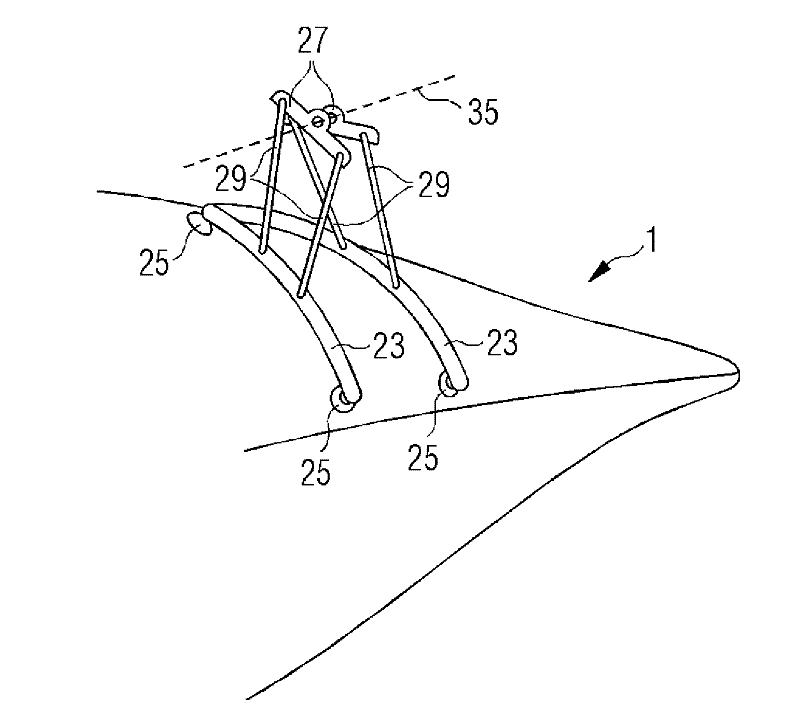
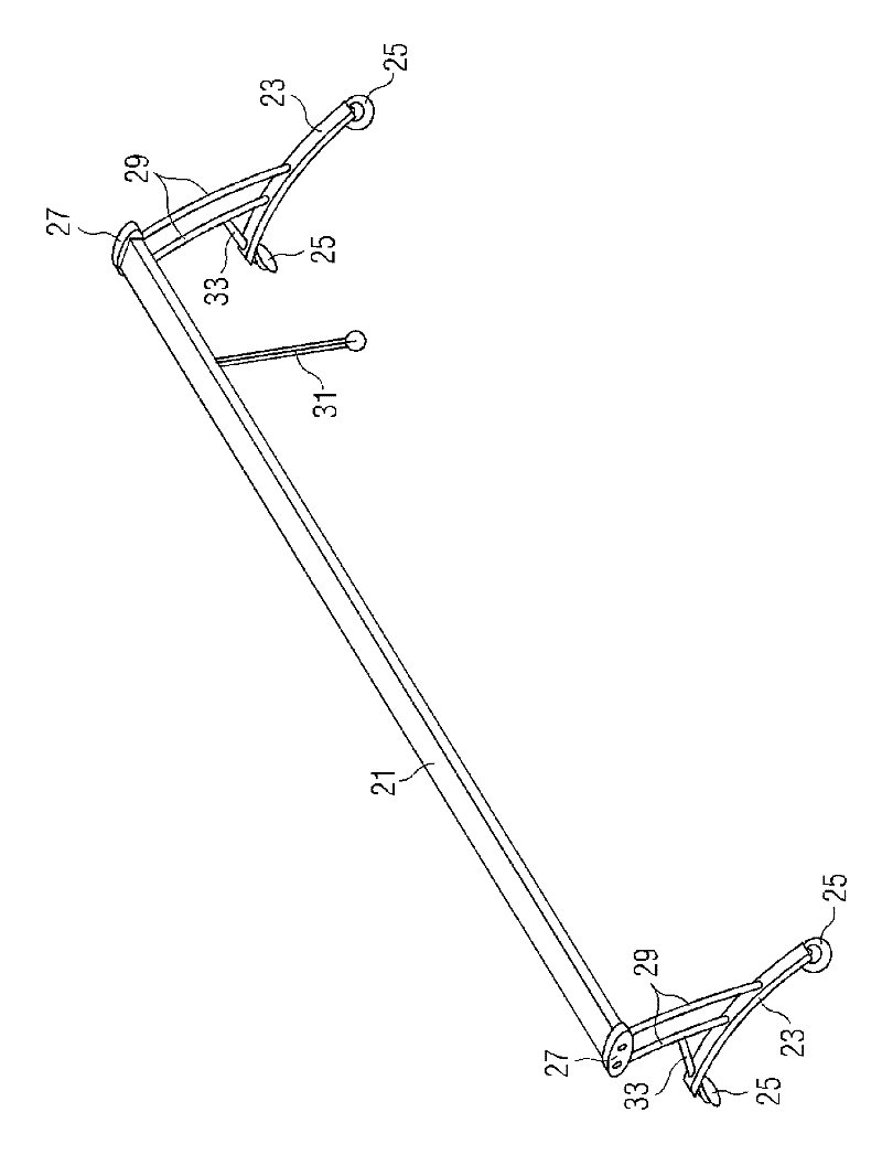
[0029] In the following, reference will be made to Figures 1 to 3 The method of the present invention is described with reference to Figures 4 to 6 Auxiliary equipment for performing the method is described.
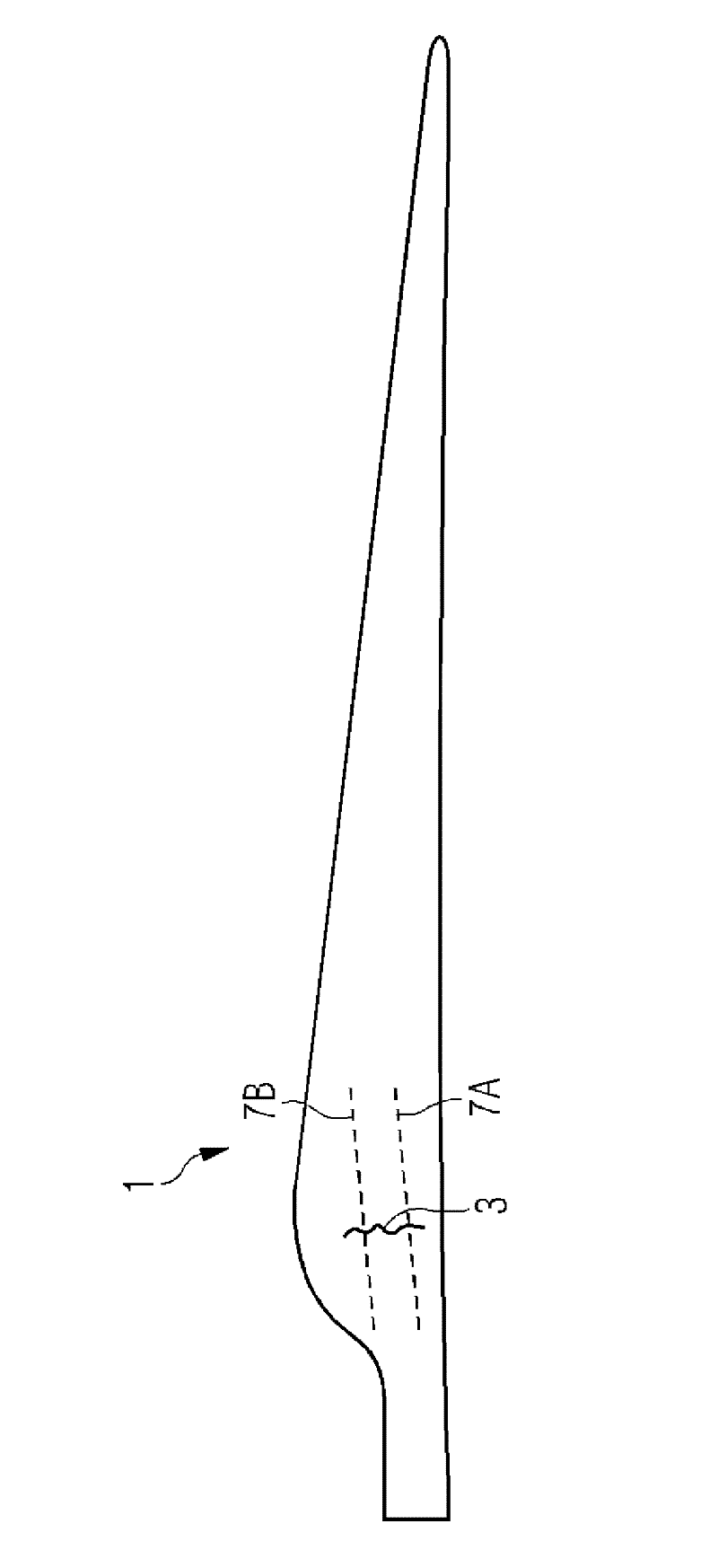
[0030] figure 1 A wind turbine rotor blade 1 made of a fiber reinforced laminate structure is shown. This rotor blade will be inspected for the presence of wrinkles in the laminate. Let us assume that the fold 3 is present in the region of the rotor blade 1 with its shoulder 5 .
[0031] To detect possible wrinkling, at least those areas of the rotor blade stack that are known to be prone to wrinkling are inspected. Since the folds usually have a longitudinal extension, such as image 3 As shown, it is sufficient to inspect the rotor blade along a single path that intersects the wrinkle. However, in order not to miss a wrinkle, the blade needs to be inspected along two or more paths that are close enough to each other to ensure that no wrinkle is missed. figure ...
PUM
 Abstract
Description
Claims
Application Information
 - R&D Engineer
- R&D Manager
- IP Professional
- Industry Leading Data Capabilities
- Powerful AI technology
- Patent DNA Extraction
Browse by: Latest US Patents, China's latest patents, Technical Efficacy Thesaurus, Application Domain, Technology Topic, Popular Technical Reports.
© 2024 PatSnap. All rights reserved.Legal|Privacy policy|Modern Slavery Act Transparency Statement|Sitemap|About US| Contact US: help@patsnap.com