
Method and device for ultrasonic testing

An ultrasonic and pulse detection technology, used in measuring devices, solids analysis using sonic/ultrasonic/infrasonic waves, material analysis using sonic/ultrasonic/infrasonic waves, etc., which can solve problems such as long detection time and inability to detect

Inactive Publication Date: 2012-08-22
INTELLIGENDT SYST & SERVICES
View PDF6 Cites 16 Cited by
  • Summary
  • Abstract
  • Description
  • Claims
  • Application Information

AI Technical Summary

Problems solved by technology

A disadvantage of this known detection method is the relatively long detection time, since the borehole surface is scanned eg helically
Furthermore, the detection of the condition via the substitute reflector results in only a weak or even no detection of actual defects with other reflective properties

Method used


Image

  • Method and device for ultrasonic testing
  • Method and device for ultrasonic testing
  • Method and device for ultrasonic testing

Examples


Embodiment Construction

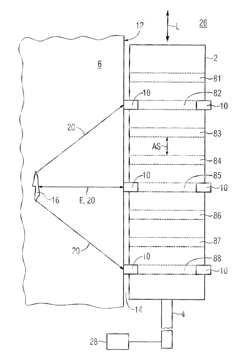
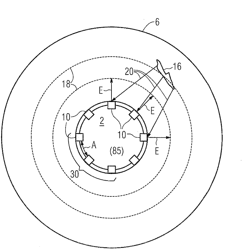
[0047] figure 1 The probe 2 in the bore 26 is shown in longitudinal section. The probe 2 is inserted into the hole 26 by means of the rod 4 of the test gun. Alternatively, the probe 2 is inserted into the hole 26 by means of a push / pull device using a flexible shaft. The test object should be, for example, a hollow shaft 6 with an axial center hole 26 . The probe 2 has eight sensor rings 81 to 88 arranged one behind the other in the axial direction L. In the illustrated embodiment, the axial direction L of the hole coincides with the central longitudinal axis of the probe 2 . Each sensor ring 81 to 88 has eight ultrasonic transducers 10 that function both as ultrasonic transmitters and ultrasonic receivers. The position of the ultrasonic transducer 10 in the circumferential direction of the sensor rings 81 to 88 changes from one sensor ring 81 to 88 to the next sensor ring. This results in figure 1 Only the ultrasonic transducers 10 of the sensor rings 82 , 85 and 88 are...


PUM


Abstract

The invention relates to a method for ultrasonically testing a test specimen (6), which comprises a bore (26) extending in an axial direction (L), wherein the probe (2) is disposed inside the bore (26) and extends in the axial direction (L). The probe (2) comprises a plurality of sensor rings (81-88) disposed behind one another in the axial direction (L) and spaced apart from each other, said sensor rings extending in a plane perpendicular to the axial direction (L) and comprising a plurality of ultrasonic transducers (10) spaced apart from each other. The ultrasonic transducers (10) are disposed in a segment (30) of a particular sensor ring (81-88), which extends in the circumferential direction of the particular sensor ring (81-88) on at least a partial section of a circumference of the particular sensor ring (81-88). For the ultrasonic testing of the test specimen (6), an ultrasonic test pulse originating from the ultrasonic transducers (10) of a segment (30) of a sensor ring (81-88) is coupled into the test specimen (6). Then a plurality of echo signals (20) are received with a first and a second ultrasonic transducer (10), wherein said transducers are disposed spatially apart from each other. The echo signals (20) are caused by reflection of the coupled-in ultrasonic test pulse from one and the same defect (16) present in the test specimen (6).

Description

technical field [0001] Method and apparatus for ultrasonic testing. Background technique [0002] Defects or imperfections in the volume and on the surface of components or technical components can be detected with the aid of ultrasound. The advantage of the pulse-echo technique, which is preferably used in ultrasonic testing, is that surface separations, such as cracks, can be detected very well. A prerequisite for reliable detection is that the defects present in the test piece are properly scanned by the acoustic waves. Ultrasonic testing can be used both in manufacturing as an integrated test for quality assurance and as a periodic test in the field of repair and maintenance to ensure the suitability of the test object for continued use. [0003] In principle, only defects for which ultrasonic echoes are received are detected in ultrasonic testing by the pulse echo method. The question of whether ultrasonic echoes reflected by defects can be detected by means of the d...

Claims


Application Information

Patent Timeline
Patent Type & Authority Applications(China)
IPC IPC(8): G01N29/22G01N29/26G01N29/265G01N29/06
CPCG01N29/069G01N29/225G01N29/262G01N29/265G01N2291/044G01N2291/106G01N2291/2636
Inventor G·恩格尔F·莫尔M·克勒宁K·M·雷迪
Owner INTELLIGENDT SYST & SERVICES
Learn More