
Pressure regulation mechanism for inflatable in-ear device

A technology of pressure regulation and internal devices, which is applied in the field of tailor-made in-ear devices and inflatable in-ear devices, which can solve the problems of wearer's injury, over-expansion of in-ear devices, discomfort, etc.

Inactive Publication Date: 2012-08-22
SONOMAX TECH INC
View PDF9 Cites 4 Cited by
  • Summary
  • Abstract
  • Description
  • Claims
  • Application Information

AI Technical Summary

Problems solved by technology

However, when constrained within the ear canal, internal pressure can build up and cause the in-ear device to over-inflate, potentially injuring or otherwise Uncomfortable (at a pressure above the ear canal comfort limit pressure level P2), which is about 2.0 psig (relative pressure of about 14kPa)

Method used


Image

  • Pressure regulation mechanism for inflatable in-ear device
  • Pressure regulation mechanism for inflatable in-ear device
  • Pressure regulation mechanism for inflatable in-ear device

Examples


Embodiment Construction

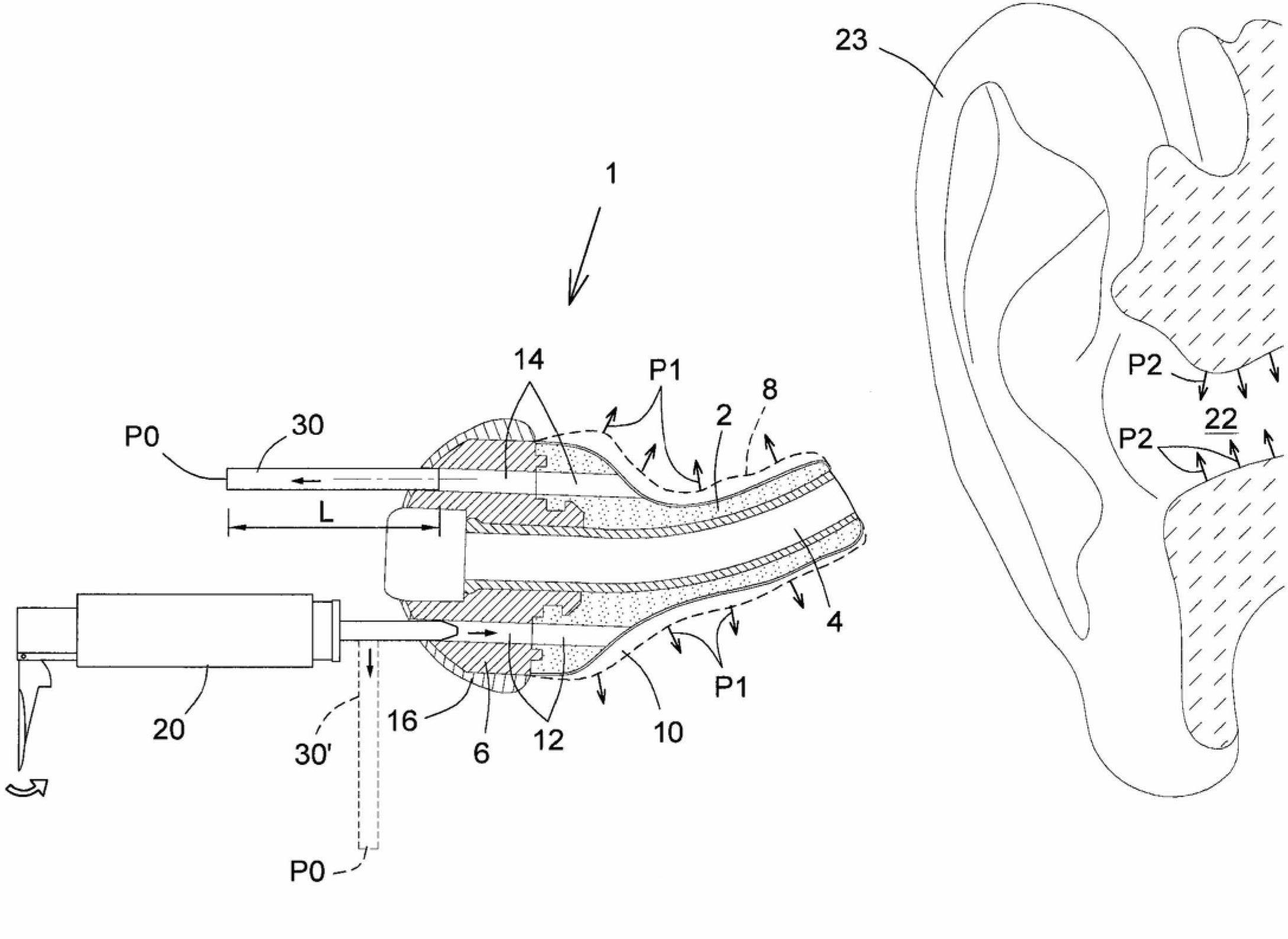
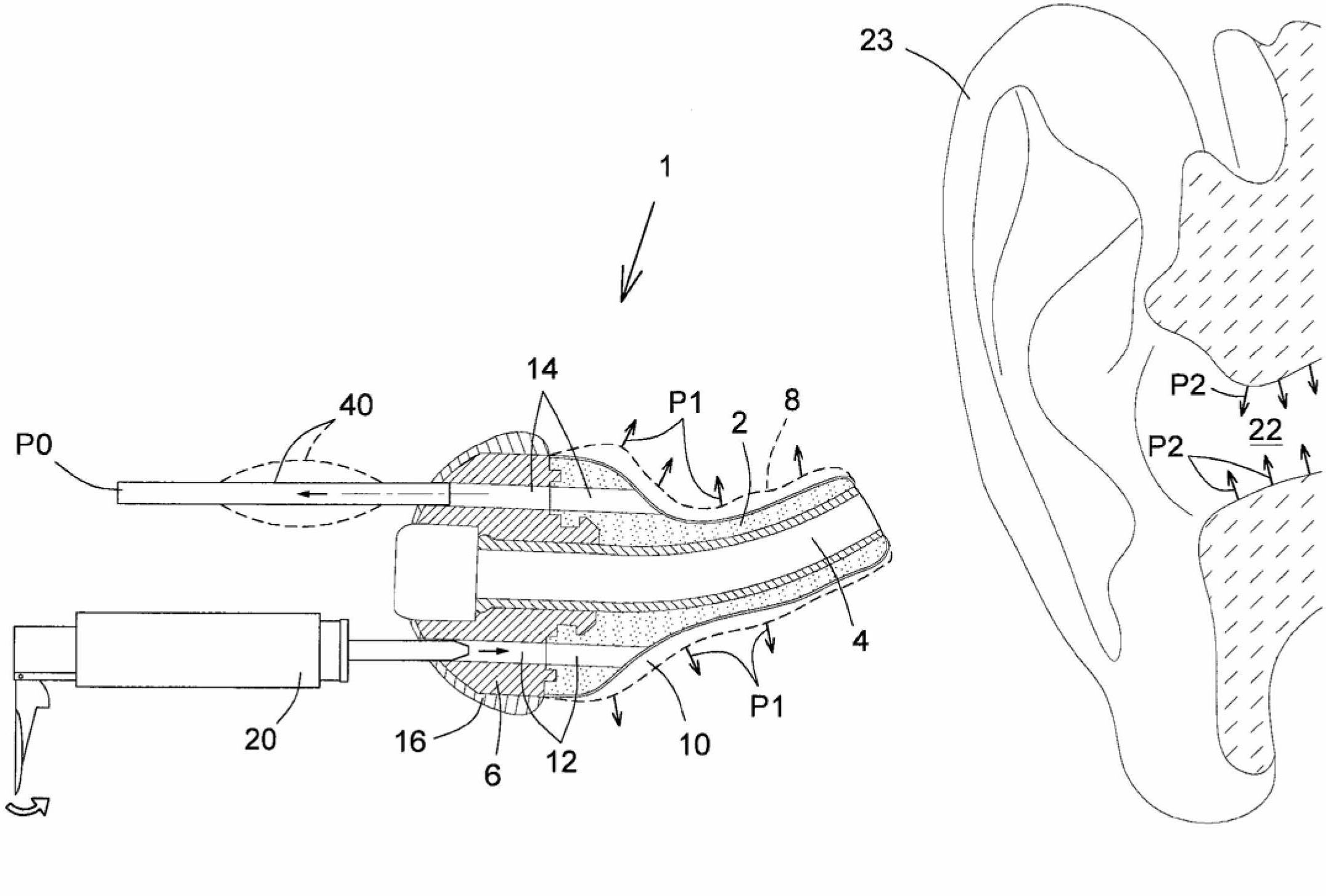
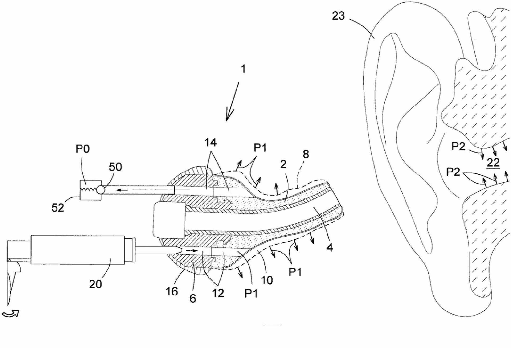
[0023] With reference to the accompanying drawings, figure 1 , figure 2 , image 3 and Figure 4 An inflatable in-ear device 1 is depicted comprising a core member 2 having an acoustic aperture 4 extending through the core member and into a platform 6 to which the core member 2 is connected. A sheath 8 of flexible material surrounds the core part 2 (for clarity, the sheath is shown not evenly spaced from the core part 2, as if the two were separated by a composite material), and said sheath A space 10 is provided for injecting a curable compound (not shown but within the body of 20 ), eg silicon compound or the like. Both the core part 2 and the platform 6 have injection channels 12 and outflow channels 14 to allow compounds to enter and exit the space 10, respectively. The platform 6 has a closure 16 formed to provide access to the inflow and outflow channels. A syringe 20 is shown as the means for injecting the compound to be used into the space 10, but it should be un...


PUM


Abstract

An inflatable in-ear device (1) incorporates a pressure regulating mechanism, for example a simple length of tubing (30) or a relief / unloader valve (50), at the inflow or outflow from the inflating sheath (8) inserted within the ear canal (22), thus allowing pressure regulation of the settable compound being injected for inflation of the sheath (8) while avoiding excesses in pressure in the inflating compound and ensuring the comfort of the individual.

Description

technical field [0001] The present invention relates to inflatable in-ear devices and, more particularly, to components of such devices for regulating and controlling the inflation pressure during inflation. [0002] In-ear devices include in-ear hearing protectors (earplugs), earphones, hearing aids, etc., and the present invention relates to tailor-made in-ear devices that are formed in situ to conform to an individual's ear canal and inside the cavum concha. Background technique [0003] The present inventors have proposed hearing protection devices that can be tailored to the individual ear, and such devices are described and claimed in US Patent Nos. 6,339,648 and 6,754,357 to McIntosh et al. These devices primarily consist of a core member around which a sheath is placed in a deflated state; a permanently curable compound injected into the cavity formed between the core member and the sheath to conform the device morphologically to the Outline of the ear canal. In t...

Claims


Application Information

Patent Timeline
Patent Type & Authority Applications(China)
IPC IPC(8): A61F11/10F16K15/20F16K17/04H04R25/02
CPCA61F11/10H04R2225/023H04R25/656A61F11/085
Inventor 迈克尔C.·特科特杰瑞米·牟伊斯
Owner SONOMAX TECH INC
Learn More