Magnetic coupling

A magnetic coupler and permanent magnet technology, applied in the direction of electrical components, electromechanical devices, etc., can solve the problems of high pressure, distribution influence, time-consuming and labor-consuming, etc., and achieve the effect of simple structure and strong reliability

Active Publication Date: 2014-06-18
HARBIN INST OF TECH
View PDF4 Cites 0 Cited by
  • Summary
  • Abstract
  • Description
  • Claims
  • Application Information

AI Technical Summary

Problems solved by technology

[0003] In the existing fixing technology of the permanent magnet on the outer rotor of the magnetic coupler, there is also a mounting hole in the middle part of the permanent magnet, and a threaded hole corresponding to the mounting hole of the permanent magnet is opened on the housing of the magnetic coupler. Screws fix the permanent magnets on the shell, and at the same time, there are non-magnetic partitions between the permanent magnets, and a protective sleeve is placed on the inner surface of the permanent magnets to realize the fixing of the permanent magnets. As far as the mounting hole is concerned, the radial force on the part around the mounting hole is relatively concentrated, and the pressure is high, which is easy to cause the permanent magnet to break and break. The existence of the mounting hole will also affect the distribution of the magnetic field, thereby affecting the performance of the magnetic coupler. It also does not play a role in hindering the sliding of the permanent magnet. For a magnetic coupler with a large number of permanent magnet poles, this permanent magnet fixing structure is time-consuming and labor-intensive, and there is also the problem of simultaneous positioning of the permanent magnet and the separator.

Method used


Image

  • Magnetic coupling
  • Magnetic coupling
  • Magnetic coupling

Examples


specific Embodiment approach 1

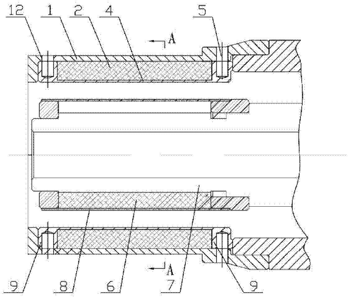
[0019] Specific implementation mode one: as Figure 1-Figure 6 As shown, a magnetic coupler, the magnetic coupler includes a housing 1, a casing 8, an inner rotor yoke 7 and several permanent magnets, and several permanent magnets include several outer permanent magnets 2 and several inner permanent magnets. magnet 6, the magnetic coupler also includes a sleeve 4, two end rings 9 and several partitions 3,

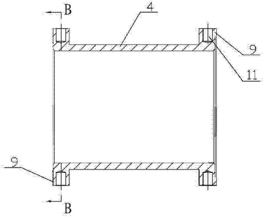
[0020] Both ends of the sleeve 4 are integrally formed with an end ring 9, the sleeve 4 is coaxially arranged with the two end rings 9, the inner diameter of the sleeve 4 is the same as that of the end ring 9, and the outer diameter of the sleeve 4 is smaller than that of the end rings 9. The outer diameter of the ring 9 and the outer circumferential surface of the end ring 9 are evenly opened with several rectangular grooves 10, and several rectangular grooves 10 are opened along the axial direction of the sleeve 4, and the several rectangular grooves 10 on the two end rin...

specific Embodiment approach 2

[0021] Specific implementation mode two: as figure 1 and image 3 As shown, in the magnetic coupler described in Embodiment 1, several threaded holes or several light holes 11 are evenly provided on the outer circumferential surface of the end ring 9, and several threaded holes 11 on the housing 1 are provided with the end ring 9. Or several connecting holes 12 corresponding to several light holes 11, the end ring 9 is connected to the housing 1 through several screws or several pins 5, which is convenient for assembly and disassembly.

specific Embodiment approach 3

[0022] Specific implementation mode three: as figure 2 As shown, in the magnetic coupling described in Embodiment 1, the outer edge of the radial cross-section of the inner rotor yoke 7 is a regular 2P polygon (2P planes are formed on the outer surface of the inner rotor yoke 7), and P is a permanent magnet pole pair number.


PUM


Abstract

A magnetic coupling relates to a transmission device, and is simple in process, easy in assembly, firm in fixing of permanent magnets, high in use reliability and capable of preventing the permanent magnets from shedding and from sliding along the surface of a rotor. Two end rings are integrally made at two ends of a sleeve respectively, a plurality of rectangular grooves are uniformly arranged on the outer circumferential surface of each end ring, partitions are axially arranged on the outer side of the sleeve, two ends of the partitions are inserted into the corresponding rectangular grooves of the end rings, a mounting groove is formed among the outer side of the sleeve, each two adjacent partitions and the two end rings, a plurality of outer permanent magnets are inlaid in the mounting grooves, the sleeve inlaid with the outer permanent magnets and the two end rings are placed in a shell together, the two end rings are connected with the shell, the outer edge of the radial cross section of an inner rotor yoke is a polygon, an inner permanent magnet is adhered on each outer side of the inner rotor yoke, the inner rotor yoke adhered with the inner permanent magnets is placed in a casing together, and the casing is placed in the sleeve. The magnetic coupling is used for motors.

Description

technical field [0001] The invention relates to a transmission device, in particular to a magnetic coupling. Background technique [0002] In the existing magnetic coupler, the permanent magnets are mostly tile-shaped structures, which are fixed on the inner surface of the outer rotor and the outer surface of the inner rotor in the form of glue. During the sticking process of the permanent magnet, the permanent magnet should be pressed tightly on the surface of the rotor until it sticks firmly. Since the polarities of adjacent permanent magnets are opposite, the attractive force generated between them will affect the positioning of the permanent magnet on the surface of the iron core. There are certain difficulties. If the number of pole pairs of permanent magnets of the magnetic coupler is large, the whole pasting process is very time-consuming and labor-intensive. The biggest weakness of the adhesive fixing form is that the adhesive is very sensitive to temperature. At hig...

Claims


Application Information

Patent Timeline
Patent Type & Authority Patents(China)
IPC IPC(8): H02K16/02
Inventor 徐永向邹继斌吴倩尚静李勇刘承军江善林赵猛王骞
Owner HARBIN INST OF TECH
Why Eureka
Try Eureka