Power factor regulating circuit and regulating method
A power factor adjustment and circuit technology, applied in the direction of reactive power adjustment/elimination/compensation, reactive power compensation, etc., to achieve the effects of small control range, considerable and convenient application, and simple control circuit
- Summary
- Abstract
- Description
- Claims
- Application Information
AI Technical Summary
Problems solved by technology
Method used
Image
Examples
Embodiment Construction
[0016] The specific embodiments of the present invention will be further described below in conjunction with the accompanying drawings, but the implementation and protection scope of the present invention are not limited thereto.
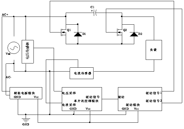
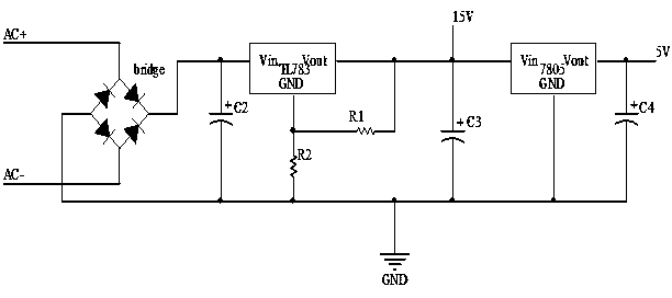
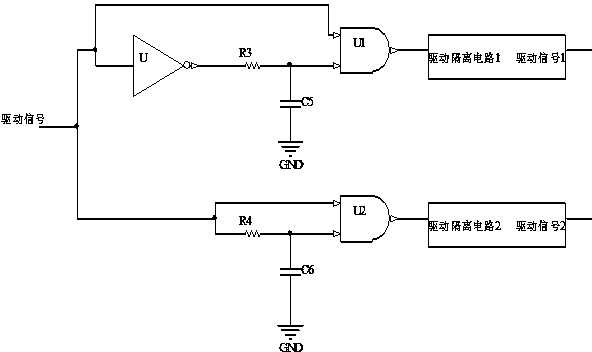
[0017] figure 1 The overall structure diagram of the power factor adjustment circuit of the example of the present invention is given, which includes a main circuit, an auxiliary power supply module, a single-chip microcomputer control module, and a drive module. The main circuit includes a first switch tube Q1, a second switch tube Q2, a first diode D1, a second diode D2, a first capacitor C1, a load, a voltage sensor, and a current sensor. The first switching tube is connected in antiparallel to the first diode, the second switching tube is connected in antiparallel to the second diode, the source of the first switching tube is connected in series with the source of the second switching tube to form a bridge arm, and the first capacitor and the br...
PUM
 Abstract
Description
Claims
Application Information
 - R&D
- Intellectual Property
- Life Sciences
- Materials
- Tech Scout
- Unparalleled Data Quality
- Higher Quality Content
- 60% Fewer Hallucinations
Browse by: Latest US Patents, China's latest patents, Technical Efficacy Thesaurus, Application Domain, Technology Topic, Popular Technical Reports.
© 2025 PatSnap. All rights reserved.Legal|Privacy policy|Modern Slavery Act Transparency Statement|Sitemap|About US| Contact US: help@patsnap.com


