
Permanent-magnet motor with integrated functions of igniting, starting and power generating

A permanent magnet motor and integrated technology, applied in the direction of electrical components, electromechanical devices, electric components, etc., can solve the problems of increasing generator cost, engine difficulty, and engine cost increase, so as to save production cost, save axial space, reduce effect of weight

Inactive Publication Date: 2013-11-27
XINGYUE GROUP
View PDF4 Cites 0 Cited by
  • Summary
  • Abstract
  • Description
  • Claims
  • Application Information

AI Technical Summary

Problems solved by technology

But there are also the following deficiencies: First, because the rotor and the stator adopt a radial magnetic circuit, both the stator and the rotor need to occupy axial space, resulting in too bloated auxiliary mechanisms such as starting, cooling, ignition and power generation, and occupying too much space. So that it is too difficult for the engine to arrange the generator and other parts, and the auxiliary mechanism is large in size, especially when used with small and compact mopeds and motorcycle engines, the proportion is out of balance.
Second, the weight is relatively heavy, and the process is relatively complicated, which virtually increases the cost of the generator, so that the cost of the engine rises, which cannot meet the requirements of low price, light weight and stable performance of small engines.
Third, on the other hand, there is a C-shaped space at the bottom of the engine case, which cannot be properly utilized because the stator cannot be installed.
For this reason, many manufacturers and people of insight carry out development and research, but there is no better solution so far

Method used


Image

  • Permanent-magnet motor with integrated functions of igniting, starting and power generating
  • Permanent-magnet motor with integrated functions of igniting, starting and power generating
  • Permanent-magnet motor with integrated functions of igniting, starting and power generating

Examples


Embodiment Construction

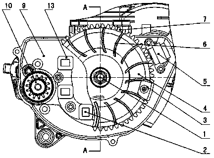
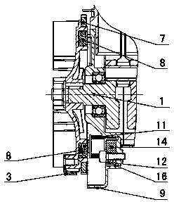
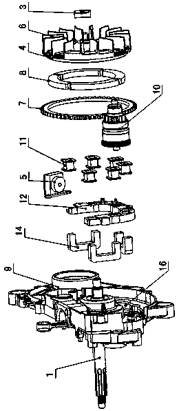
[0017] Figure 1 to Figure 7 Shown, for the present invention creates the specific implementation of the permanent magnet motor that integrates ignition, starting, and power generation, it includes casing 9, crankshaft 1, stator 2, rotor 4, starting one-way device 10, and rotor 4 is fixed on the crankshaft 1, the rotor 4 is provided with fan blades 6, magnetic tiles 8 and starting gear 7, the fan blades 6 are arranged on one side of the rotor 4 and formed with the rotor 4 at one time, and the magnetic tiles 8 are fixed on the other side of the rotor 4 In the magnetic tile groove 15, the starting gear 7 is press-fitted on the outer circumference of the rotor 4, the trigger signal plate 3 is fixed on the rotor 4, the trigger signal plate 3, the fan blade 6, the magnetic tile 8 and the starting gear 7 are connected with the The rotor 4 forms a whole and rotates together with the crankshaft 1, and the starting gear 7 meshes with the starting one-way device 10; the stator 2 include...


PUM


Abstract

The invention discloses a permanent-magnet motor with integrated functions of igniting, starting and power generating, which comprises a tank (9), a crankshaft (1), a stator (2), a rotor (4) and a starting isolator (10). The rotor (4) is provided with vanes (6), a magnetic shoe (8) and a starting gear (7), the vanes (6) are arranged on one side of the rotor (4), the magnetic shoe (8) is fixed in a magnetic shoe slot (5) of the rotor (4), and the starting gear (7) is pressed on the rotor (4). The stator (2) comprises a C-shaped coil fixing frame (12), at least three C-shaped silicon steel pieces (14), a coil holder (13) and coils (11), the C-shaped coil fixing frame (12) is fixed in a groove (16) of the tank (9), the C-shaped silicon steel pieces (14) are inlaid on the C-shaped coil fixing frame (12) and extend out of the same perpendicularly, the coils (11) are fixed on extension portions of the C-shaped silicon steel pieces (14), and the extension portions of the C-shaped silicon steel pieces (14) correspond to the magnetic shoe (8) axially. The permanent-magnet motor in the above structure has the advantages of simple and compact structure, reliability in working, small size, light weight, low cost and the like.

Description

technical field [0001] The invention relates to an accessory mechanism of a moped and a motorcycle engine, in particular to a permanent magnet motor integrating ignition, cooling, starting and power generation. Background technique [0002] Existing mopeds and motorcycle engines all use radial magnetic circuit permanent magnet motors, such as Figure 8 As shown, the iron core of the stator is evenly distributed around the cogging of the coil, and most of them use 6-level or 8-level coils to form a circle. The stator can only be installed in the axial space of the engine box through the bracket, otherwise it will be with the Interference occurs between the engine case or cylinder, and the rotor is formed by stamping and stretching process, and its magnetic tiles are evenly installed on the circumference of the inner wall of the rotor. The outer circumference of the rotor is fixedly mounted with a starting gear, which meshes with the starting one-way device. , There are evenly...

Claims


Application Information

Patent Timeline
Patent Type & Authority Patents(China)
IPC IPC(8): H02K7/116H02K1/27
Inventor 胡济荣
Owner XINGYUE GROUP
Learn More