
Vision detection system and detection method

A visual inspection and inspection system technology, applied in measuring devices, optical testing flaws/defects, instruments, etc., can solve problems such as poor inspection accuracy, low inspection efficiency, and inability to work for a long time, so as to solve positioning problems and high inspection efficiency. , compact design effect

Inactive Publication Date: 2012-08-15
SUZHOU QIANZHAO AUTOMATION TECH
View PDF7 Cites 25 Cited by
  • Summary
  • Abstract
  • Description
  • Claims
  • Application Information

AI Technical Summary

Problems solved by technology

[0002] At present, the quality inspection of the appearance and shape of the known batch products is detected by the human eye, because the judgment of the human eye is not easy to quantify and execute, the human eye is prone to fatigue, people are prone to emotions, and cannot grow in some high temperature or toxic environments. Time and work and other factors lead to a high misjudgment rate and high misjudgment rate in the quality inspection of product appearance and shape.
Some places have tried to use cameras to obtain images to replace human eye detection, but they all manually put a single product directly on the workbench for photo inspection, take it away after inspection, and put a new one, so repeat, automation The degree is low, the detection efficiency is low, the work intensity of the detection personnel is high, and the detection accuracy is poor, which cannot meet the needs of modern high-speed automated production lines

Method used


Image

  • Vision detection system and detection method
  • Vision detection system and detection method
  • Vision detection system and detection method

Examples


Embodiment Construction

[0026] The present invention will be described in further detail below in conjunction with the accompanying drawings of the specification:

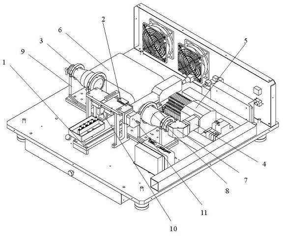
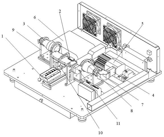
[0027] The present invention relates to a visual inspection system, which includes a frame. The inspection system also includes a transmission device, an optical imager, a light source 3 and a control device. The transmission device includes a guide rail 1, a servo motor (not shown in the figure), The transmission device is arranged on the frame, the optical imager is arranged above and in front of the frame, the light source 3 is arranged opposite to the optical imager, and the control device is arranged on the frame and connected with the optical imager. In the present invention, the The optical imager is a digital camera.

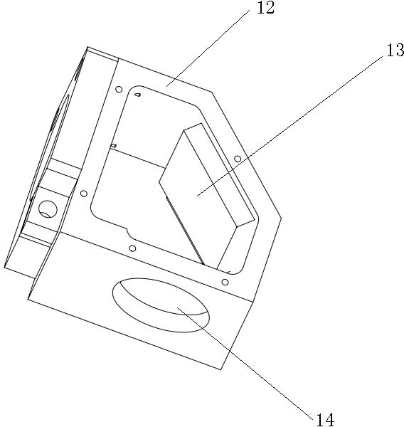
[0028] In the present invention, the detection system further includes a corner device 7 including a body and a prism. Two holes are provided on two opposite surfaces of the body. The prism is arranged in the body and th...


PUM


Abstract

The invention relates to a vision detection system. The vision detection system comprises a rack, a digital camera, a light source, a PLC (Programmable Logic Controller), an industrial personal computer, a steering device and a lens, as well as a support, a stepping motor, an ejecting device and an optical fiber sensor, wherein the steering device comprises a device body and a prism, and the light source and the lens are arranged on the support. The light source is a bilateral telecentric light source, and the lens is a bilateral telecentric lens. The ejecting device is arranged on a guide rail and controlled by the stepping motor, and the optical fiber sensor is arranged above the guiderail and controlled by the PLC. In addition, the invention further discloses a detection method of the vision detection system. Compared with the prior art, the vision detection system has high detection efficiency, is accurate, does not need manual intervention, effectively solves the positioning problem of products to be detected through the arrangement of the ejecting device, leads the camera to be horizontally arranged by the arrangement of the steering device, thus greatly saving the space of the device and enabling the design to be more compact.

Description

Technical field [0001] The invention relates to a detection device, specifically, a device that uses vision to detect parts, and the invention discloses its detection method. Background technique [0002] At present, the quality inspection of the appearance and shape of the well-known batch products are all detected by the human eye. Because the judgment of the human eye is not easy to quantify and execute, the human eye is prone to fatigue, people are prone to emotional, and some high temperature or toxic environments cannot be long. Time work and other factors have led to a high rate of misjudgment and misjudgment in the quality inspection of product appearance and appearance. In some places, there have been attempts to use cameras to acquire images to replace human eye detection, but they all manually place a single product directly on the workbench for photographic inspection, take it away after the inspection, and put a new one. This is repeated and automated. The detection...

Claims


Application Information

Patent Timeline
IPC IPC(8): G01N21/89G01B11/24
Inventor 周建东李高阳林天伟
Owner SUZHOU QIANZHAO AUTOMATION TECH
Learn More