Condensation cavity for gas water heater and manufacturing technology thereof

A gas water heater and processing technology, applied in fluid heaters, applications, household appliances, etc., can solve the problems of difficult operation, time-consuming and laborious, and low production efficiency for workers, so as to improve product competitiveness, easy for workers to operate, and reduce production costs. The effect of product cost

Inactive Publication Date: 2012-08-15
林慧贤
View PDF4 Cites 1 Cited by
  • Summary
  • Abstract
  • Description
  • Claims
  • Application Information

AI Technical Summary

Problems solved by technology

The existing condensing cavity is composed of an upper cover, a bucket body and a lower cover. A rubber ring is installed between the upper cover and the bucket body, and high-temperature silica gel is coated on the joint between the two to make the seam tightly sealed. Water leakage; there is also a rubber ring between the lower cover and the barrel body, and high-temperature silica gel is also coated on the joint between the two to make the seam seal watertight; the production process is on the upper cover-the barrel- After adding a rubber ring between the lower covers, apply high-temperature silica gel to make the joints sealed and watertight. The above-mentioned condensation chamber and its processing technology have the following defects: 1) The production efficiency is low, and the waiting time for drying after painting is too long, Time-consuming and labor-intensive; a single shift can produce up to 150 units; 2) The coating process is cumbersome and difficult for workers to operate; 3) Silicone has a peculiar smell, which has an impact on the working environment; 4) Silicone will age, and leakage and cracks will occur after aging, affecting The tightness of the parts; 5) The appearance of the parts is not beautiful and cannot fully meet the high requirements of the product

Method used


Image

  • Condensation cavity for gas water heater and manufacturing technology thereof
  • Condensation cavity for gas water heater and manufacturing technology thereof

Examples


Embodiment Construction

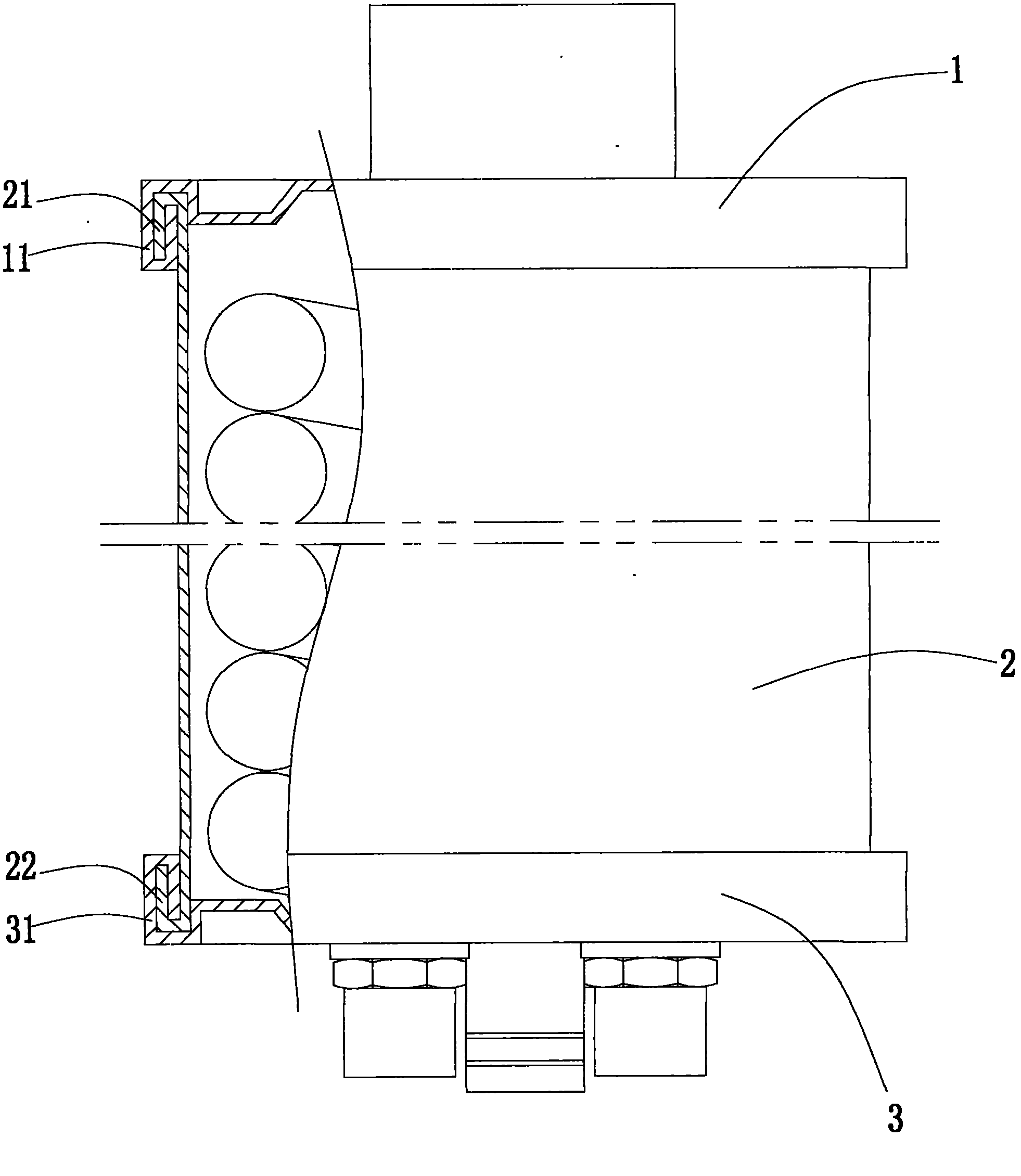
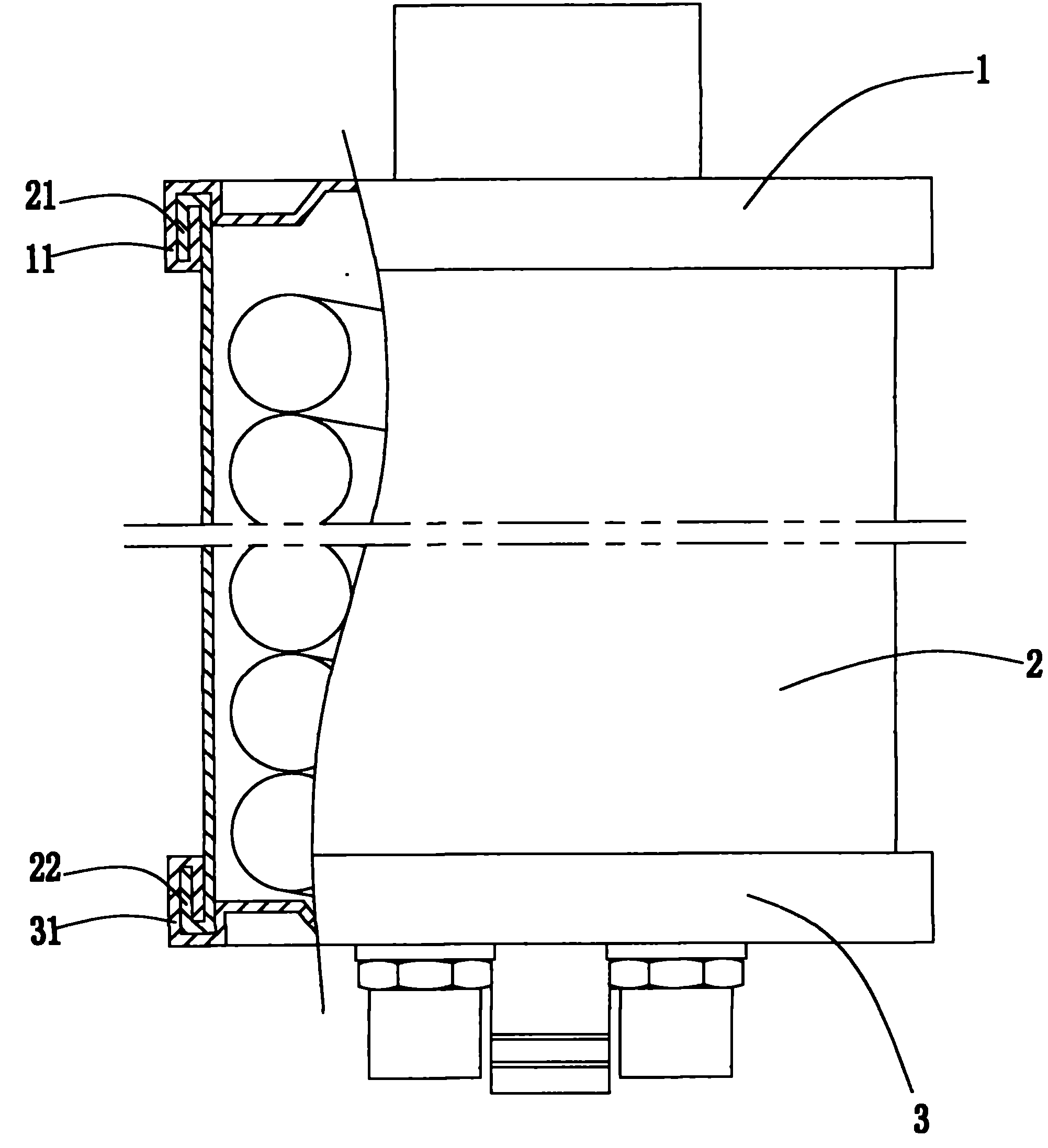
[0014] Such as figure 1 As shown, the condensing chamber for a gas water heater of the present invention includes an upper cover 1, a barrel body 2 and a lower cover 3, the upper cover 1 is provided with a first flange 11, and the barrel body 2 is provided with a second flange 21 and a third flange. Flange 22, the lower cover 3 is provided with a fourth flange 31, the first flange 11 of the upper cover 1 and the second flange 21 of the barrel body 2 are tightly crimped together by a rolling machine; the fourth flange of the lower cover 3 The folded edge 31 and the third folded edge 22 of the barrel body 2 are tightly crimped together by a rolling machine. Both the first folded edge 11 of the upper cover 1 and the fourth folded edge 31 of the lower cover 3 are bent inward; the second folded edge 21 and the third folded edge 22 of the barrel body 2 are bent outward.

[0015] A process for processing a condensing cavity for a gas water heater, comprising the following process st...


PUM


Abstract

The invention relates to a condensation cavity for a gas water heater, wherein the condensation cavity for the gas water heater comprises an upper cover, a cylinder body and a lower cover, wherein the upper cover is provided with a first folding edge; the cylinder body is provided with a second folding edge and a third folding edge; the lower cover is provided with a fourth folding edge; the first folding edge of the upper cover and the second folding edge of the cylinder body are tightly jointed together in a compression mode through a roller press; and the fourth folding edge of the lower cover and the third folding edge of the cylinder body are tightly jointed together in a compression mode through the roller press. Compared with the prior art, the condensation cavity for the gas water heater provided by the invention has the following beneficial effects: 1) the roller press is utilized for compression joint production, the production efficiency is improved by 4-5 times, and the single-batch output production capability can reach more than 600 units; 2) high-temperature silicon gel is not required for sealing, the condensation cavity for the gas water heater not only is environmentally-friendly, but also is clean, and has no foreign smell and pollution, the technology is simple, and the operation for workers is easy; 3) a rubber ring and high-temperature silicon gel are omitted, and hazards of aging, leakage, bursting and the like do not exist; 4) the product cost is lowered, and the product competitiveness is improved; and 5) the product appearance is improved greatly, and the requirements of higher-level products can be met. The invention also relates to a manufacturing technology of the condensation cavity for the gas water heater.

Description

technical field [0001] The invention relates to a gas instant water heater, in particular to a condensing chamber for a gas water heater and a processing technology thereof. Background technique [0002] The condensing gas instant water heater is a newly developed product in recent years. It has become the most energy-saving product of the new generation because of its heat exchange efficiency of over 95%. The "condensing chamber" is the most critical part of the water heater. The quality of the most important parts of the heat exchange efficiency directly affects the heat exchange efficiency of the whole machine. The existing condensing cavity is composed of an upper cover, a bucket body and a lower cover. A rubber ring is installed between the upper cover and the bucket body, and high-temperature silica gel is coated on the joint between the two to make the seam tightly sealed. Water leakage; there is also a rubber ring between the lower cover and the barrel body, and hig...

Claims


Application Information

Patent Timeline
Patent Type & Authority Applications(China)
IPC IPC(8): F24H9/00B21D39/00B21D51/34
Inventor 林慧贤林志祥
Owner 林慧贤
Why Eureka
Try Eureka