
Well structure for delaying casing damage on fault

A technology of wellbore structure and faults, applied in wellbore/well components, production fluids, earthwork drilling, etc., can solve problems such as failure to prevent fault slippage, casing damage at faults, failure to prevent fault shear slippage, etc.

Inactive Publication Date: 2012-08-15
CHINA UNIV OF PETROLEUM (EAST CHINA) +2
View PDF4 Cites 9 Cited by
  • Summary
  • Abstract
  • Description
  • Claims
  • Application Information

AI Technical Summary

Problems solved by technology

[0003] Numerical simulations and field tests show that the strength of the casing-cement system cannot prevent fault shear slip
Because the shear area of ​​the fault slip is too large, the use of high-strength casing cannot prevent the slip of the fault, but can only delay its progress to a certain extent
Therefore, simply improving the strength of the casing cannot fundamentally solve the problem of casing damage at the fault.

Method used


Image

  • Well structure for delaying casing damage on fault
  • Well structure for delaying casing damage on fault
  • Well structure for delaying casing damage on fault

Examples


Embodiment Construction

[0014] The present invention will be described in detail below in conjunction with specific examples.

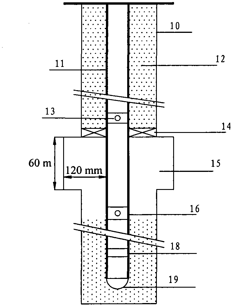
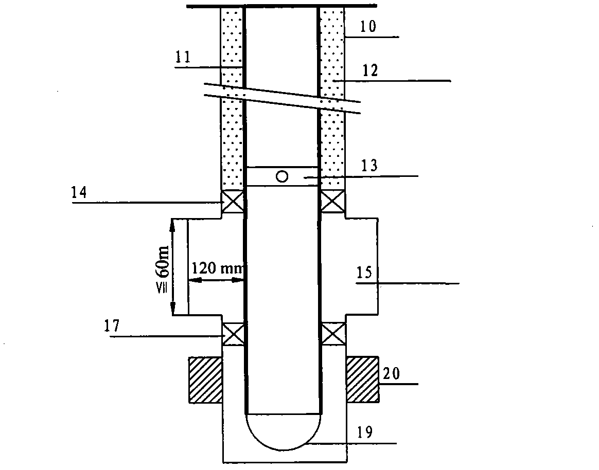
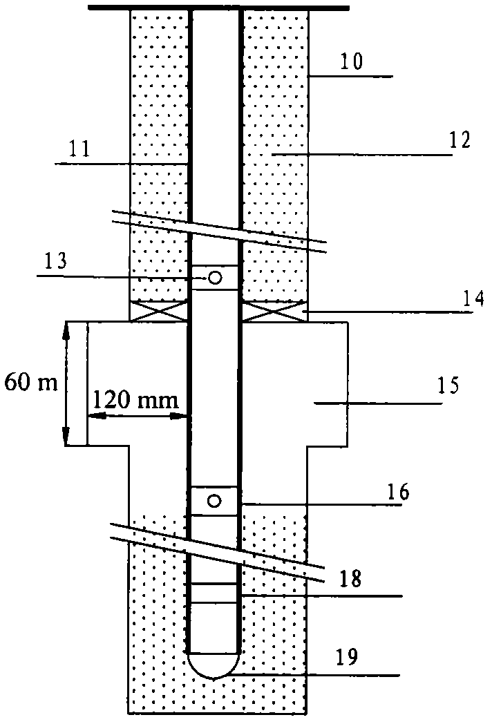
[0015] In order to delay casing damage at faults, the present invention proposes a new wellbore structure for drilling at faults: no cementing in the 30m interval above and below the breakpoint encountered in drilling, and reaming while drilling is adopted to make the gap between the casing and the formation The gap reaches 120mm, leaving a buffer zone for the movement of the formation along the fault to prevent the casing from being sheared and damaged.

[0016] 1. Reaming operation

[0017] Considering the risk and cost of reaming comprehensively, it is proposed to use the reaming-while-drilling technology to ream the interval 30m above and below the breakpoint.

[0018] Reaming-while-drilling construction process: Before the tool enters the well, ensure that the reaming-while-drilling bit can be retracted freely → lower the reaming-while-drilling tool to the predetermine...


PUM


Abstract

The invention discloses a well structure for delaying casing damage on a fault. According to the structure, the well cementation is not performed on sections 30m above and below a drill-in breakpoint, and the broaching is performed in a drilling manner, so that a gap between a casing and the stratum reaches 120mm, and a buffer zone is reserved for the motion of the stratum along the fault so as to prevent the casing from being damaged by shear. According to the technical scheme, the gap between the casing and the stratum reaches 120mm, and the buffer zone is reserved for the motion of the stratum along the fault so as to prevent the casing from being damaged by shear.

Description

technical field [0001] The invention relates to a well body structure for delaying casing damage at faults. Background technique [0002] Faults are stress concentration areas. During the long-term large-area water injection development process of the oilfield, the injected water will suppress the pressure of the formation near the fault, and the formation pressure on the two sides of the fault will lose balance, which will aggravate the stress concentration. When the stress exceeds the strength of the fault surface, it will inevitably appear. The relative dislocation of the upper and lower walls of the fault locally releases energy, resulting in damage to the casing of the oil-water well drilled into the fault. [0003] Numerical simulations and field tests show that the strength of the casing-cement system cannot prevent fault shear slip. Because the shear area of ​​the fault slip is too large, the use of high-strength casing cannot prevent the slip of the fault, but can ...

Claims


Application Information

Patent Timeline
Patent Type & Authority Applications(China)
IPC IPC(8): E21B43/00
Inventor 张卫东杨勇王建龙刘新华路智勇张艳增
Owner CHINA UNIV OF PETROLEUM (EAST CHINA)
Learn More