Quick arc-shaped raised-edge drill rod dismounting device and method

A dismantling device and arc-shaped technology, which is applied to drill pipes, drill pipes, drilling equipment, etc., can solve the problems of long disassembly process, high labor intensity of workers, frequent safety accidents, etc., to shorten disassembly time and simple structure , The effect of low processing cost

Active Publication Date: 2012-08-15
重庆南桐机械制造有限责任公司
View PDF7 Cites 6 Cited by
  • Summary
  • Abstract
  • Description
  • Claims
  • Application Information

AI Technical Summary

Problems solved by technology

However, the cross-section shape and size of the arc-shaped convex-edged drill pipe are quite different from those of the conventional cylindrical drill pipe. During the disassembly process of the drill pipe, the chuck of the power head of the drilling rig does not match the circular-arc-shaped convex-edged drill pipe, and the power of the original drilling rig cannot be used. The system realizes automatic disassembly, which must be disassembled manually with a dead wrench. The disassembly process takes a long time, the labor intensity of the workers is high, and safety accidents occur frequently

Method used


Image

  • Quick arc-shaped raised-edge drill rod dismounting device and method
  • Quick arc-shaped raised-edge drill rod dismounting device and method
  • Quick arc-shaped raised-edge drill rod dismounting device and method

Examples


Embodiment Construction

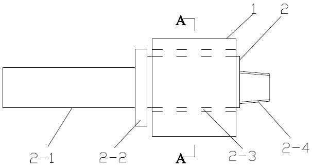
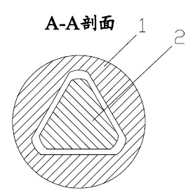
[0021] Such as figure 1 and figure 2 As shown in the figure, a quick release device for a circular-arc-shaped ribbed drill pipe includes a triangular sleeve 1 and a triangular shaft 2. The triangular sleeve 1 can slide axially on the triangular shaft 2, but cannot move relative to the triangular shaft 2. Circumferential rotation. The triangular shaft 2 is divided into four sections: cylinder section 2-1, limit plate 2-2, prism section 2-3, and external thread section 2-4, each of which is connected by welding.

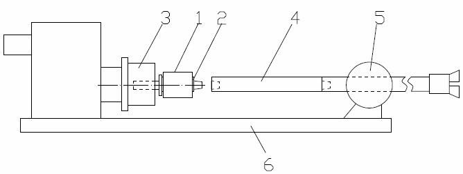
[0022] Such as image 3 , Figure 4 As shown, the cylindrical section 2-1 of the triangular shaft 2 is connected with the drill chuck 3, and rotates in the circumferential direction or moves axially together with the drill chuck 3, and the limit plate 2-2 cooperates with the end face of the drill chuck. In the limit, the external thread section 2-4 of the triangular shaft 2 can be connected with the arc-shaped convex rib drill rod 4; The cross-sectional shape and...


PUM


Abstract

The invention relates to quick arc-shaped raised-edge drill rod dismounting device and method. The quick arc-shaped raised-edge drill rod dismounting device comprises a three-edge shaft and a trigonal shaft, wherein the three-edge shaft is divided into a cylinder section, a limit disc, a prism section and an external thread section, the cylinder section is used for being connected with a drilling machine chuck so as to perform circumferential rotation or axial movement along with the drilling machine chuck, and the external thread section is used for being connected with an arc-shaped raised-edge drill rod; and the section shape and size of the prism section are identical with those of the arc-shaped raised-edge drill rod. The dismounting method of the device comprises the following steps of: after the drilling construction is completed, installing the three-edge shaft and the trigonal shaft on a drilling machine power head chuck, pushing the power head chuck to a drill rod position, forwarding the chuck so as to enable the three-edge shaft and the drill rod to be connected and not to be screwed up tightly, dragging the drill rod to the drill rod position, sliding the trigonal shaft to be sheathed at the position at which the three-edge axis and the drill rod are connected, clamping a drilling machine holder, reversing the drilling machine chuck, opening the connection between the first drill rod and the second drill rod, manually reversing and taking down the first drill rod, and repeating the steps until all the drill rods are dismounted. The device can be used for greatly reducing the safety dismounting danger while improving the drill rod dismounting efficiency.

Description

technical field [0001] The invention relates to a drilling machine component used in mine production, in particular to a dismantling device for an arc-shaped convex rib drilling rod of a hydraulic drilling machine used in mine construction drainage drilling. Background technique [0002] Coal mine gas drainage mainly uses hydraulic drilling rigs to drill holes in the coal (rock) layer to relieve the pressure of the coal seam gas and achieve the purpose of gas control. For a long time, drill pipes with cylindrical cross-sections have been mainly used in drainage drilling construction. Dozens to hundreds of drill pipes are often required to construct a drainage borehole. The removal of drill pipes mainly depends on the chuck and holder of the drill head. The drilling rig is disassembled by its own power. [0003] In recent years, a circular-arc-shaped convex-edged drill pipe has appeared in the drilling construction of coal rock formations. This drill pipe has been gradually ...

Claims


Application Information

Patent Timeline
Patent Type & Authority Applications(China)
IPC IPC(8): E21B19/16
Inventor 陈久福张赛黄德辉孙大发龙建明李文树高明郑伟刘钊
Owner 重庆南桐机械制造有限责任公司
Why Eureka
Try Eureka