
Combined jig with overturn function

A combined fixture and function technology, applied in the field of combined fixtures with flip function, can solve problems such as affecting operation, occupying a lot of space, and different fixture structures, reducing labor intensity, saving space, and reasonable structure design. Effect

Inactive Publication Date: 2012-08-15
LC TIANJIN ELECTRONICS PLASTIC PRODS
View PDF6 Cites 5 Cited by
  • Summary
  • Abstract
  • Description
  • Claims
  • Application Information

AI Technical Summary

Problems solved by technology

During the assembly process, jigs are usually used to fix the blank to prevent the position of the blank from changing, otherwise it will not only affect the operation, but also the quality of the product cannot be guaranteed
But, there is following problem in this fixture of prior art at present: when product is different, the structure of fixture also can be different, usually a kind of product needs to configure a set of fixture, when the production variety of factory is many, these fixture It takes up a lot of space to store it when not in use temporarily, and it is not easy to find
In addition, when it is necessary to replace the products produced, the jig must be replaced. If the number of replacements is frequent, it will undoubtedly increase the labor intensity of the operator.

Method used


Image

  • Combined jig with overturn function
  • Combined jig with overturn function

Examples


Embodiment Construction

[0009] The combined jig with flip function provided by the present invention will be described in detail below in conjunction with the accompanying drawings and specific embodiments.

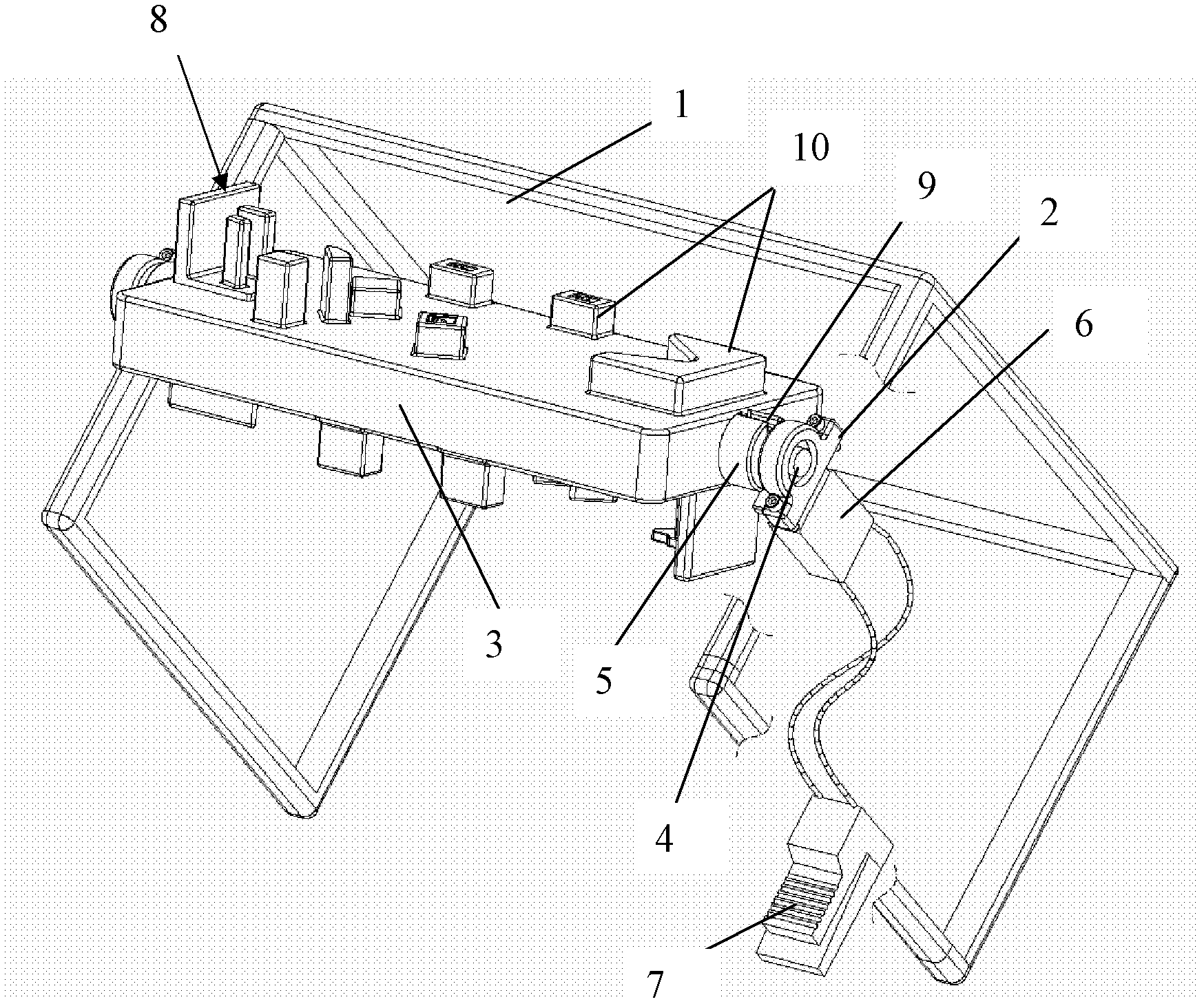
[0010] Such as figure 1 As shown, the combined jig provided by the present invention includes a bracket 1, two bearings 2, a base plate 3, a rotating shaft 4, a limit block 5, a pneumatic positioning pin 6, a pedal 7 and two sets of jigs 8; The lower end of the bracket 1 is set on the ground; two bearings 2 are symmetrically installed on both sides of the bracket 1; the base plate 3 is rectangular; The two ends of 4 are installed on two bearings 2 respectively; the limit block 5 is annular, and is set on the rotating shaft 4 between one end of the base plate 3 and the adjacent bearing 2, and its outer circumferential surface is along the length A limit groove 9 is formed in the direction; a pneumatic positioning pin 6 that can lock or release the upper limit groove 9 of the limit block 5 is ins...


PUM


Abstract

The invention discloses a combined jig with an overturn function, and the combined jig comprises a bracket, two bearings, a base plate, a rotating shaft, a spacing block, a pneumatic locating pin, a pedal and two jigs, wherein the lower end of the bracket is arranged on the ground; the two bearings are installed on two sides of the bracket; the rotating shaft is arranged on the middle position in the base plate in a penetrating manner; two ends of the rotating shaft are respectively installed on the two bearings; the spacing block is annular and is sheathed on the rotating shaft positioned between one end of the base plate and the bearing adjacent to the base plate; a spacing groove is formed along the length direction of the outer circumstance surface of the spacing block; the lower part of the bracket on one end of the spacing block is provided with the pneumatic locating pin which can lock or loosen the spacing groove on the spacing block; the pedal is arranged on the ground and is connected with the pneumatic locating pin; and the two jigs are respectively installed on the front side and back side of the base plate. Therefore, a great quantity of occupied space can be saved, and the labor intensity of operation personnel can be lightened.

Description

technical field [0001] The invention belongs to the technical field of automobile manufacturing, and in particular relates to a combined jig with a turning function. Background technique [0002] A car is a vehicle that uses combustible gas as power, or is equipped with a power drive device, generally has four or more wheels, and travels on land without relying on rails or wires. There are many kinds of accessories installed in the car, some of which are made by assembly, that is, the blank is first made by injection molding or mechanical method, and then the required parts are assembled on the blank to make the finished product. During the assembly process, jigs are usually used to fix the blank to prevent the position of the blank from changing, otherwise not only will the operation be affected, but the quality of the product cannot be guaranteed. But, there is following problem in this fixture of prior art at present: when product is different, the structure of fixture a...

Claims


Application Information

Patent Timeline
IPC IPC(8): B25B11/02
Inventor 胡明
Owner LC TIANJIN ELECTRONICS PLASTIC PRODS
Learn More