
Casing-less, long-spiral concrete secant pile construction method

A construction method and concrete technology, applied in sheet pile wall, foundation structure engineering, construction and other directions, can solve the problems of easy partial fork and lap joint effect, low construction work efficiency, high construction cost, and ensure construction quality and water-stop effect. , Conducive to civilized construction management and environmental protection, the effect of improving construction efficiency

Inactive Publication Date: 2012-08-08
吴传清 +1
View PDF0 Cites 11 Cited by
  • Summary
  • Abstract
  • Description
  • Claims
  • Application Information

AI Technical Summary

Problems solved by technology

[0004] The current problems of occlusal pile technology in the industry are: 1. The pile body materials of occlusal piles are mainly ordinary underwater concrete, ultra-retarded concrete, cement soil or soil-curing agent mixture; 2. The most widely used construction equipment It is an (integrated or separated) casing drilling rig, and some patented technologies use multi-axis drilling rigs for construction; 3. Except for some patented technologies, the construction technology basically uses two-sequence piles in sequence and interval construction; 4. The construction cost is relatively high 5. The construction efficiency is not high; 6. The occlusal pile constructed by the casing drilling rig is easy to deviate when the pile depth is large, which makes the lap joint effect unsatisfactory

Method used


Image

  • Casing-less, long-spiral concrete secant pile construction method
  • Casing-less, long-spiral concrete secant pile construction method
  • Casing-less, long-spiral concrete secant pile construction method

Examples


Embodiment Construction

[0022] Below in conjunction with embodiment the present invention is further described.

[0023] A construction method for a long spiral concrete occlusal pile without casing, comprising the following construction steps:

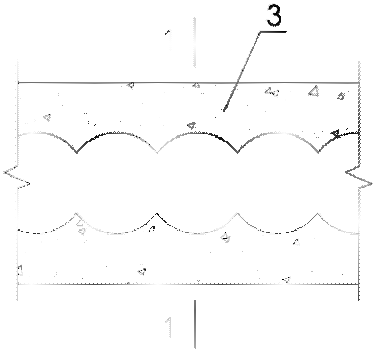
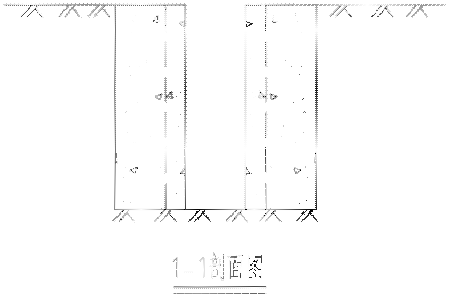
[0024] A. Measure and place the pile position, and the adjacent pile bodies are occluded and overlapped;

[0025] B. The long auger pile driver is in place and centered; when the pile driver travels to the vicinity of the pile position, the chassis of the long auger drill is flat, the tower is vertical and the drill point is aligned with the center point of the pile through adjustment;

[0026] C. Drilling to the design depth;

[0027] D. After drilling to the design depth, lift the drill bit up 0.2m ~ 1m, and then use the concrete delivery pump to transport the concrete to the bottom of the hole through the concrete hose and hollow drill pipe;

[0028] E. After the concrete is poured to the opening of the operation surface, the machine is moved;

[0029]...


PUM


Abstract

A casing-less, long-spiral concrete secant pile construction method relates to the construction of concrete secant pile structures in the field of construction projects. The construction method includes the following steps: (A) pile positions are determined, and neighboring pile bodies are secantly lapped; (B) a long-spiral drilling machine is mounted in place and aligned; when the long-spiral drilling machine is moved to nearby a pipe position, the chassis of the long-spiral drilling machine is adjusted to be flat, the tower of the long-spiral drilling machine is adjusted to be vertical, and the drill bit of the long-spiral drilling machine is adjusted to be aimed at the center of a pile; (C) a hole is drilled by a designed depth; (D) after the hole is drilled by the designed depth, the drill bit is lifted up by 0.2m to 1m, and a concrete pump is then used for feeding concrete to the bottom of the hole via a concrete hose and a hollow drill stem; (E) after the concrete is filled to the orifice of the operating face, the long-spiral drilling machine is moved; (F) the long-spiral drilling machine is moved to the next pile position, and steps B, C, D and E are repeated. According to the method, not only the construction quality and the water-stopping effect are better guaranteed, but also the construction efficiency is greatly increased, the cost is lower, and the method is more favorable for on-site civilized construction management and environment protection.

Description

technical field [0001] The invention relates to the construction technology of concrete occlusal pile structures in the field of construction engineering. Background technique [0002] As the new retaining structure or waterproof and anti-seepage structure of the occlusal pile has the function of water and soil retaining at the same time, the water-stop effect is more reliable than other water-stop structures, and the soil retaining capacity is close to that of the underground diaphragm wall structure and higher than other support structures. , the cost is between the underground diaphragm wall and other supporting structures, so it is very competitive in ultra-deep foundation pit support engineering and anti-seepage and water-proof engineering, and is more and more valued by the industry. [0003] At present, there have been more than ten patent applications on the subject of "occlusal piles", such as: "a construction method for occlusal piles suitable for soft soil and soi...

Claims


Application Information

Patent Timeline
Patent Type & Authority Applications(China)
IPC IPC(8): E02D5/36E02D19/18
Inventor 吴传清申华容申华兵王林莫明君胡晓霜陶琨刘凤桂正华
Owner 吴传清
Learn More