
Cable laying method and bracket thereof

A cable laying and cable technology, which is applied in the field of cable laying and its support, can solve the problems of difficulty and large longitudinal induced voltage of the cable aluminum sheath, and achieve the effects of reducing induced voltage, good energy saving effect, and reducing civil construction costs

Inactive Publication Date: 2015-05-06
李超 +2
View PDF5 Cites 0 Cited by
  • Summary
  • Abstract
  • Description
  • Claims
  • Application Information

AI Technical Summary

Problems solved by technology

[0011] The technical problem to be solved by the present invention is that the longitudinal induction voltage of the cable aluminum sheath is relatively large during multi-circuit laying; it is difficult or even impossible to realize the mutual offset to the minimum or for the existing cable arrangement and arrangement after cross-connection in a whole cycle section. Zero, poor energy saving effect; the layout of existing shielded wires and return wires is also difficult to make the return wire or shielded wires have no induced voltage and loss when the cable is working normally

Method used


Image

  • Cable laying method and bracket thereof
  • Cable laying method and bracket thereof
  • Cable laying method and bracket thereof

Examples


Embodiment Construction

[0023] The present invention will be further described below in conjunction with accompanying drawing.

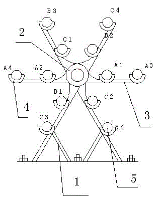
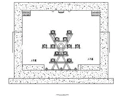
[0024] like figure 1 As shown, the cable laying bracket of the present invention includes a bracket main body 1, and twelve cable support seats 2 and a central ring 3 arranged on the support main body 1, and every three cable support seats 2 form a group, and the cable support seats 2 Arranged along the circumferential direction of the concentric circles, and the same group of cable support seats 2 are located on the same circumference, and the angle between them is 120°; the central ring 3 is located at the center of the aforementioned concentric circles; the concentric circles include inner rings And the outer ring, six cable support seats 2 are respectively established on the inner and outer rings, and are evenly arranged along the inner and outer rings.

[0025] When in use, four sets of three-phase cables can be placed on the cable laying bracket to place the cables 5...


PUM


Abstract

The invention discloses a cable laying method and a bracket thereof. More than one group of three-phase cables is arranged along the circumference direction of a concentric circle, so that the same group of three cables is arranged on the same circumference, and included angles between every two cables are 120 DEG. The bracket has the advantages of simple structure, low cost, minimum longitudinal induced voltage, and better energy saving effect because longitudinal induced voltages in the whole circulating section are mutually cancelled out as smallest as possible, even zero.

Description

technical field [0001] The invention relates to a cable laying method and its support. Background technique [0002] The existing power cable laying methods are generally divided into three types: direct buried cables, laying through pipes, and laying in tunnels. [0003] The three-phase cables of each circuit are generally arranged in layers: the arrangement is horizontal, vertical and triangular. [0004] When the AC working current or fault current flows through the cable core wire, it will form self-inductance and mutual inductance alternating magnetic flux, which will generate an induced electromotive force on its own metal sheath, that is, self-inductance potential; The mutual induced electromotive force is generated on the metal sheath of the cable, that is, the mutual inductance potential. This induced potential is distributed along the cable axis, so it is called longitudinal induced electromotive force. At this time, if two points of the cable metal sheath are gr...

Claims


Application Information

Patent Timeline
Patent Type & Authority Patents(China)
IPC IPC(8): H02G3/04
Inventor 李超徐艺李有胜
Owner 李超
Learn More