
Throat-type inlet manifold of electrical control fuel jet-type internal combustion engine

A fuel injection and intake manifold technology, applied in the direction of combustion air/combustion-air treatment, mechanical equipment, engine components, etc., can solve the problems of limited improvement of mixing efficiency, increase of overall structure volume, and increase of mixing time, etc. Achieve the effects of reducing harmful gas emissions, saving fuel and improving performance

Inactive Publication Date: 2012-08-01
张伟
View PDF1 Cites 1 Cited by
  • Summary
  • Abstract
  • Description
  • Claims
  • Application Information

AI Technical Summary

Problems solved by technology

Although this disclosed technology can improve the mixing efficiency of the fuel air in the manifold channel to a certain extent, improve the performance of the engine, reduce fuel consumption, and reduce the emission of harmful gases, but between the intake manifold and the cylinder head The structure of adding a manifold block and a suction regulator inside the manifold block has a complex structure, high cost, and the increase in the overall structure volume requires a large space for use, and the mixing efficiency is optimized by extending the mixing channel of fuel and air In this way, the improvement of mixing efficiency is limited, which not only increases the mixing time but also prolongs the time for the mixed gas to enter the combustion chamber

Method used


Image

  • Throat-type inlet manifold of electrical control fuel jet-type internal combustion engine
  • Throat-type inlet manifold of electrical control fuel jet-type internal combustion engine
  • Throat-type inlet manifold of electrical control fuel jet-type internal combustion engine

Examples


Embodiment

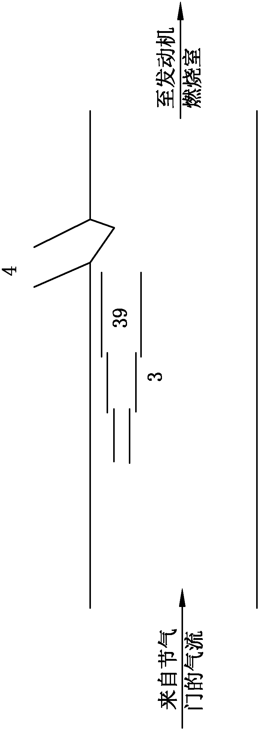
[0031] The electronically controlled fuel injection type internal combustion engine throat type intake manifold of the present invention, as attached figure 1 , attached figure 2 As shown, it includes a body 2, which is provided with several passages 21, 22, 23, 24 communicating with the combustion chamber of the engine, and an oil injector 4 is arranged in the passages 21, 22, 23, 24, and each passage One or more throats 3 are also provided, and the throats 3 have diversion holes 39 , the diversion holes 31 are arranged along the air intake direction and the outlets at the front end thereof are close to the injection ports of the fuel injection nozzles 4 . The cross-section of the diversion hole 31 can be circular, elliptical or other shapes, and the diameter of the outlet end of the diversion hole 31 is larger than the diameter of the inlet end.

[0032] When there are multiple throats 3 , the multiple throats 3 are arranged in a fan shape and surround the fuel injection n...


PUM


Abstract

The invention relates to a throat-type inlet manifold of an electrical control fuel jet-type internal combustion engine, which comprises an inlet manifold body, wherein a plurality of channels communicated with a combustion chamber of the engine are arranged on the body, injection nozzles and one or a plurality of throats are arranged in the channels, the throats are provided with flow-guiding holes, the flow-guiding holes are arranged along the air inlet direction, and front outlets of the flow-guiding holes are close to the injection orifices of the injection nozzles. The high speed airflow of the throats enables the oil mist of the injection nozzles to be subjected to secondary atomization, and mixing efficiency of fuel and air is improved significantly, so that performance of the engine is enhanced, fuel is saved, harmful gas emission of the engine is lowered, and starting and acceleration performance of cars and ships using the internal combustion engine as power can be improved and fuel consumption thereof can be reduced without changing the working capacity of cylinders. The throats are arranged in the channels of the inlet manifold, so that outer space of the engine is not occupied, and capacity of the cylinders is not changed.

Description

technical field [0001] The invention relates to the technical field of internal combustion engines for vehicles and ships, in particular to an electronically controlled fuel injection type internal combustion engine throat type intake manifold. [0002] Background technique [0003] Since the advent of internal combustion engines, people have made many improvements in their fuel supply, from carburetors to single-point electronically controlled fuel injection, multi-point electronically controlled fuel injection, and direct injection in cylinders. Reduction of exhaust emissions provides a reliable guarantee. [0004] Conventional fuel injection systems are usually adapted to monitor the amount of fuel supplied to the engine or its cylinders, and to control the timing and length of each injection to make the cylinders have the desired fuel / air mixture; conventional injector systems are usually not It is designed to optimize the mixing of fuel and air upstream of the cylinde...

Claims


Application Information

Patent Timeline
IPC IPC(8): F02M35/104F02M29/00
Inventor 张伟
Owner 张伟
Learn More