
Large-span continuous steel truss girder arch pushing device

A steel truss girder and large-span technology, which is applied in the field of large-span continuous steel truss girder with vault push device, can solve the problems of reducing construction efficiency, affecting the overall stability of steel truss girder, and failing to meet the requirements of the designed bridge, so as to achieve saving Cost, effect of simplifying construction

Active Publication Date: 2012-08-01
STEEL STRUCTURE CONSTR CO LTD OF CHINA TIESUU CIVIL ENG GRP
View PDF6 Cites 13 Cited by
  • Summary
  • Abstract
  • Description
  • Claims
  • Application Information

AI Technical Summary

Problems solved by technology

However, in some steel truss girder jacking constructions, the steel truss girder and the flexible arch are pushed synchronously, and the center of gravity of the beam is at a higher position. Protective devices, which will not only affect the overall stability of the steel truss girder, reduce construction efficiency, but also fail to meet the design requirements of the bridge

Method used


Image

  • Large-span continuous steel truss girder arch pushing device
  • Large-span continuous steel truss girder arch pushing device
  • Large-span continuous steel truss girder arch pushing device

Examples


Embodiment Construction

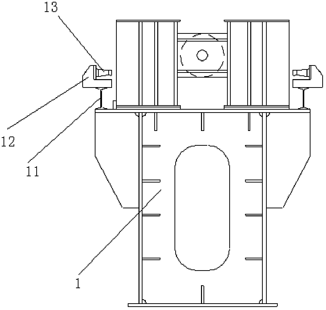
[0026] Referring to the accompanying drawings, a large-span continuous steel truss girder belt vault push device includes a sliding device and a main pushing system device. The sliding device includes left and right longitudinal slideway beams 1, 2, and a slider 3. The inner edges of the left and right longitudinal slideway beams 1 and 2 are respectively provided with longitudinal full-length limit stops 4, and the inner wall of the slider 3 is placed on the longitudinal full-length limit stop 4, and the left and right longitudinal The top surface of the slideway beam is laid with a longitudinal stainless steel main slideway, and the ends of the left and right longitudinal slideway beams are provided with a lifting protection pier 5, the lifting protection pier 5 is less than the height of the slider 3, and the outside of the slider is provided with The deviation correction device is divided into tracking deviation correction device and fixed deviation correction device. The fi...


PUM


Abstract

The invention discloses a large-span continuous steel truss girder arch pushing device, which comprises a slip device and a main pushing system device, wherein the slip device comprises a left longitudinal slipway girder, a right longitudinal slipway girder and a slide block; the inner edges of the left longitudinal slipway girder and the right longitudinal slipway girder are provided with a longitudinal full-length limiting stop block respectively; the inner side wall of the slide block is pressed against the longitudinal full-length limiting stop block; deviation correction devices are arranged on the outer side of the slide block and are divided into a tracking deviation correction device and a fixed deviation correction device; the end parts of a plurality of horizontal traction ropes which are led out of a horizontal continuous jacking jack are fixedly connected to a C-shaped counterforce seat; and a piston rod of the jacking jack is just opposite to the bottom of a lower chord node of a steel truss girder. According to the large-span continuous steel truss girder arch pushing device, in-place pushing of the steel truss girder and a flexible arch is realized by using the steel truss girder arch pushing device, so that the steel truss girder and the flexible arch are integrally stable during pushing construction, the linear shape is good, and the pushing quality is guaranteed.

Description

technical field [0001] The invention relates to the technical field of bridge steel structure installation, and is particularly suitable for a large-span continuous steel truss beam with arch jacking device in the construction of a large-span steel truss beam with arch multi-point continuous jacking method. Background technique [0002] In the construction of steel bridges, long-span steel truss girders are often constructed by multi-point continuous jacking, and the steel truss girders are finally installed by pulling the steel truss girders through jacking jacks. [0003] The current steel girder jacking is all pushed into position parallel to the truss girder, and the center of gravity of the beam is relatively low. The jacking device is set with a jacking slideway and slider according to the position of the center of gravity of the steel truss girder, and there is no jacking limit device, timely tracking and correcting device and vertical protection device for landing be...

Claims


Application Information

Patent Timeline
Patent Type & Authority Applications(China)
IPC IPC(8): E01D21/06
Inventor 方继张庆发张雪松张时利梁崇双宋进军开前正邢文斌李刘玉
Owner STEEL STRUCTURE CONSTR CO LTD OF CHINA TIESUU CIVIL ENG GRP
Learn More