
Longitudinal rotary transformer screw propeller

A propeller, longitudinal rotation technology, applied in the directions of rotating propellers, propellers, rotary propellers, etc., can solve the problems of reduced maneuverability and load capacity, limited number of rotor blades, and poor maneuverability of military models, and achieves increased maneuverability. The effect of performance, strong competitiveness, and strong maneuverability

Inactive Publication Date: 2012-08-01
张岳
View PDF6 Cites 3 Cited by
  • Summary
  • Abstract
  • Description
  • Claims
  • Application Information

AI Technical Summary

Problems solved by technology

It can be seen that 3 / 4 of the effective fluid power is not utilized
[0021] (2). The area of ​​the propeller is too large, and the installation and use are greatly restricted
[0023] (3). The action direction of the existing propeller hydrodynamic force is not easy to change
[0030] (4). The rolling tendency of the helicopter propeller, that is, the forward blade and the backward blade due to the difference in lift force, is not easy to solve fundamentally
[0033] (5). The tail rotor of existing helicopters not only consumes power, increases parts, operation complexity and body weight, but also is prone to failure
[0048] Second, MD's airflow elimination type tailless rotor technology is only available in the United States, but because firstly, this technology needs to occupy more power of the engine, resulting in insufficient reserve power, reduced maneuverability and load capacity; secondly, the airflow without tail rotor The design destroys the tail flow separation of the original rotor system and damages the flight performance of the helicopter
Therefore, the tailless rotor technology cannot be applied to large and medium-sized helicopters, nor does it have high maneuverability.
Its corresponding models such as MD500N, MD600N and MD900 / 902 series are all light and small without exception, and there are no military models due to poor maneuverability
[0049] Third, the shortcomings of Boeing's tandem dual-rotor technology are mainly due to the complexity of the mechanical structure, resulting in high costs and difficult maintenance
[0055] (1): Due to the complex structure, it is difficult to manufacture, manipulate and maintain;
[0056] (2): It needs to occupy more power of the engine, resulting in insufficient reserve power and reduced load capacity;
[0057] (3): The relevant design has destroyed the tail airflow separation of the original helicopter rotor system and damaged the flight performance of the helicopter;
[0058] (4): The number of rotor blades is greatly limited;
[0059] It is not difficult to see from the above introduction that the existing technology for eliminating the tail rotor cannot guarantee that its comprehensive advantages are greater than that of the tail rotor technology

Method used


Image

  • Longitudinal rotary transformer screw propeller
  • Longitudinal rotary transformer screw propeller
  • Longitudinal rotary transformer screw propeller

Examples


Embodiment 1

[0211] aircraft:

[0212] Aircraft that move in the atmosphere include balloons that are lighter than air, such as airships, and rockets that do not require air as an oxidant, but mainly refer to aircraft. From the perspective of wings, aircraft are divided into three categories: fixed-wing aircraft, helicopters, and rotorcraft.

[0213] The rotorcraft utilizes the relative air flow when flying forward to blow the rotor to rotate to generate lift. It is a kind of aircraft between the fixed-wing aircraft and the helicopter. Its rotor is actually a propeller without power, and there is nothing unique in theory. Although the gyroplane has some advantages, so it has not disappeared at present, but its disadvantages are more fatal, so it is still not a climate. Its speed is slow, the range is short, and it cannot avoid nearby obstacles; although it is very similar to a helicopter, it can neither take off vertically nor hover, and its maneuverability is very poor; compared with fl...

Embodiment 2

[0261] car:

[0262] The main advantage of the present invention in the automobile field should be in " all-terrain vehicle " aspect.

[0263] The so-called all-terrain vehicle is defined as "a vehicle suitable for all terrains" (English All Terrain Vehicle, abbreviated ATV).

[0264] At present, the mainstream driving mode of automobiles is wheel drive. This is also the only mainstream driving method for automobiles. Other driving methods such as track drive, jet drive, etc. cannot and cannot replace the dominance of wheel drive.

[0265] The principle of wheel drive is that the tires exert force on the ground, and the ground exerts a reaction force on the tires. This reaction force is the real force driving the car.

[0266] Every car wants this counterforce to be strong enough. To make the reaction force strong enough, the action force must first be strong enough. But for all-terrain vehicles, this problem is not the most important. Otherwise, wouldn't any high-powered...

Embodiment 3

[0282] ship:


PUM


Abstract

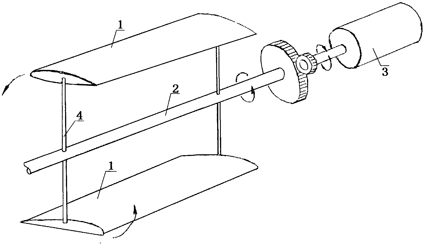
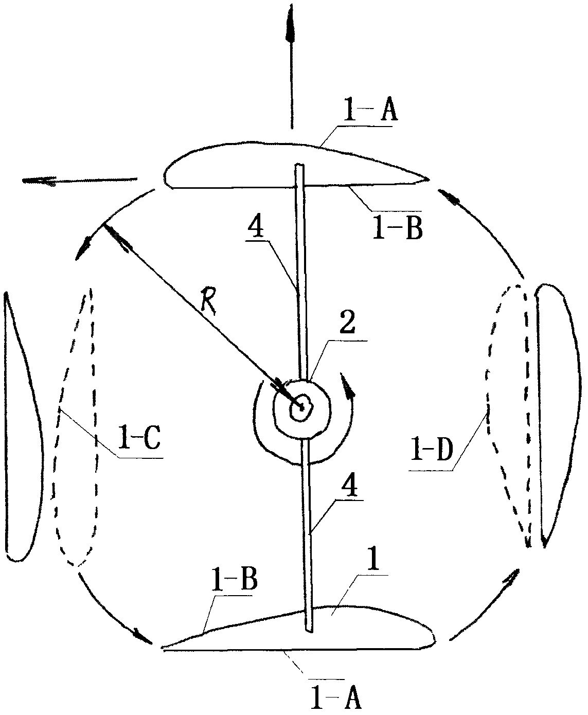
The invention discloses a completely new concept screw propeller. The device is provided with a plurality of blades; and the blades are connected with an engine transmission shaft through a connecting rod. The screw propeller is characterized in that: a revolving trail of the blades is in the shape of a three-dimensional cylinder, but the revolving trail of the blades of the conventional screw propeller is in the shape of a circular platform; the cylinder formed by the revolving trail of the screw propeller is parallel to an engine power output shaft connected with the connecting rod, but the circular plane formed by the revolving trail of the blades of the conventional screw propeller is perpendicular to the engine power output shaft; the blades of the screw propeller periodically deform when doing work, but the blades of the conventional screw propeller do not deform generally when doing work; and the screw propeller can be used for driving an airplane, a ship, a vehicle or other devices moving with hydrodynamic force. The revolving mode of the screw propeller differs in fundamental significance from the conventional screw propeller; and the screw propeller has the superior functions which are not owned by the conventional screw propeller.

Description

technical field [0001] The invention relates to a device for generating fluid power, in particular to a device for generating fluid power by utilizing the rotation and deformation of propellers. Background technique [0002] Propellers have a long history. It has been 260 years since marine propellers came out (1752, Bernoulli, Switzerland), and it has been nearly 110 years since air propellers came out (1903, American Wright Brothers). If counting from the "bamboo dragonfly", air propellers have been around for at least 1,700 years (the "flying car" in "Baopuzi" by Ge Hong (283-343) of the Eastern Jin Dynasty is recognized as a bamboo dragonfly. Although Ge Hong described "Flying car", but not necessarily the inventor of the thing, and the invention time must be earlier than the recorded time.). [0003] In the history of at least hundreds of years, both marine propellers and air propellers have undergone countless developments and evolutions. However, these developments...

Claims


Application Information

Patent Timeline
Patent Type & Authority Applications(China)
IPC IPC(8): B64C11/00B64C11/16B63H1/14B63H1/26B63H1/28
Inventor 张岳
Owner 张岳
Learn More