Water vapor transfer-separator plate arrangement

一种分离器、侧分离的技术,应用在固体电解质电池的电解质处理、最终产品制造、电化学发生器等方向,能够解决昂贵、耗时、增加分离器板总体尺寸等问题

Active Publication Date: 2012-07-25
GM GLOBAL TECH OPERATIONS LLC
View PDF4 Cites 0 Cited by
  • Summary
  • Abstract
  • Description
  • Claims
  • Application Information

AI Technical Summary

Problems solved by technology

This method is time consuming and expensive to manufacture, repair or replace
Additionally, the use of plastic plates increases the overall size of the separator plate

Method used


Image

  • Water vapor transfer-separator plate arrangement
  • Water vapor transfer-separator plate arrangement
  • Water vapor transfer-separator plate arrangement

Examples


Embodiment Construction

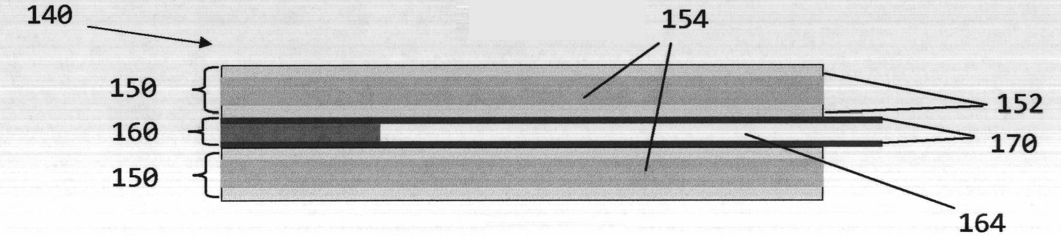
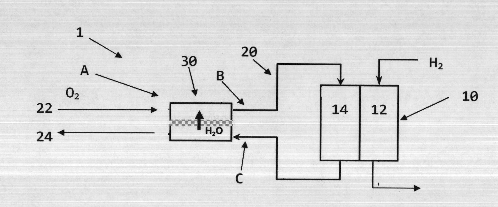
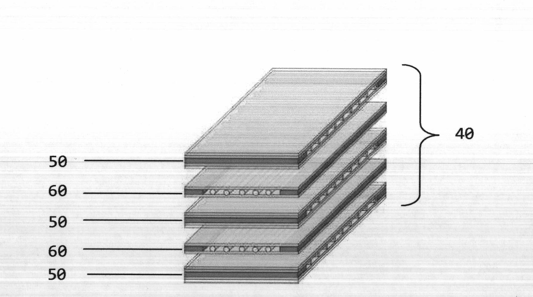
[0051] First refer to figure 1 , a fuel cell system 1 consisting of a fuel cell stack 10 is shown, including a number of individual fuel cells, each having an anode 12 and a cathode 14 . Each flow path is used to transport reactants and their by-products to and from the respective anode 12 and cathode 14 . The WVT unit 30 is fluidly coupled to appropriate portions of the flow path 20 to facilitate moisture exchange between the exhaust 24 and the supply 22 . As shown specifically at cathode 14, dry air from a compressor (not shown) is supplied to WVT unit 30 through feed 22 within a range of pressures and low humidity (typically about 0%). Similarly, the exhaust from cathode 14 reaches WVT unit 30 through exhaust 24 . The cathode exhaust 24 is at a lower pressure and higher humidity than the air entering the WVT unit 30 on the feed 22 side. Within the WVT unit 30 is a core consisting of a number of wet-side and dry-side plates stacked in an alternating arrangement such that ...


PUM


Abstract

The arrangement (140) has separator plates (150, 160) defining a region of a wet-side flow channel (154). Water vapor transfer (WVT) membranes (170) are arranged on surfaces of the separator plates so that a region of a common, planar, dry-side flow channel (164) is formed between the transfer membranes. Edge strips are positioned between the membranes so that the dry-side flow channel region is formed. A thickness of the dry-side flow channel region is defined by the strips. An individual support e.g. thread, is positioned below the dry-side flow channel region. An independent claim is also included for a method for manufacturing a WVT arrangement. The thread is made of plastic, distributed adhesive or glass.

Description

[0001] This application claims the benefit of the filing date of US Provisional Application No. 61 / 434,569, filed January 20, 2011. technical field [0002] The present invention relates generally to methods of improving the transport of water vapor produced by fuel cells, and more particularly to improved water vapor transport (WVT) separator plate assemblies and methods of making such assemblies. Background technique [0003] In many fuel cell systems, hydrogen or hydrogen-enriched gas is supplied to the anode side of the fuel cell through a flow field, while oxygen (eg, in the form of atmospheric oxygen) is supplied to the cathode side of the fuel cell through a separate flow field. A suitable catalyst (eg, platinum) is typically provided as a layer on a porous diffusion medium, typically made of carbon fabric or paper, so that it exhibits elasticity, electrical conductivity, and air permeability. Catalytic diffusion media are used to facilitate hydrogen oxidation at the ...

Claims


Application Information

Patent Timeline
Patent Type & Authority Applications(China)
IPC IPC(8): H01M8/04
CPCH01M2008/1095H01M8/0267H01M8/0228Y02E60/50H01M8/04291H01M8/0258Y10T156/1026Y10T156/1089Y02P70/50H01M8/0297
Inventor D·A·马丁彻克T·D·布伦彻蒂
Owner GM GLOBAL TECH OPERATIONS LLC
Why Eureka
Try Eureka