Device for carrying out heat exchange between gas and solid particulate matters

A solid particle, one-stage heat exchange technology, applied in heat exchanger types, direct contact heat exchangers, lighting and heating equipment, etc., can solve the problem of poor preheating effect, uneven preheating of powder materials, spreading The machine cannot guarantee the complete dispersion of powder, etc., so as to avoid loss, reduce preheating energy consumption, and improve preheating yield.

Active Publication Date: 2012-07-25
卓卫民
View PDF6 Cites 0 Cited by
  • Summary
  • Abstract
  • Description
  • Claims
  • Application Information

AI Technical Summary

Problems solved by technology

[0007] The first technical problem to be solved by the present invention is that in the prior art, the cement raw meal is easy to gather on the shrinkage slope to form a block or agglomerate. The heat exchange is conducted in direct contact with the gas, but its interior cannot fully contact the hot flue gas, so the preheating effect is not good, which leads to uneven preheating of the powder, although there is a spreader in the preheating cylinder for dispersing Agglomerated powder, but powder lumps or lumps are still easy to fall from the gap of the spreader, and the spreader cannot guarantee complete dispersion of the aggregated powder; thus providing a way to make the powder evenly pre- Heat exchange device between hot gas and solid particles

Method used


Image

  • Device for carrying out heat exchange between gas and solid particulate matters
  • Device for carrying out heat exchange between gas and solid particulate matters
  • Device for carrying out heat exchange between gas and solid particulate matters

Examples


Embodiment Construction

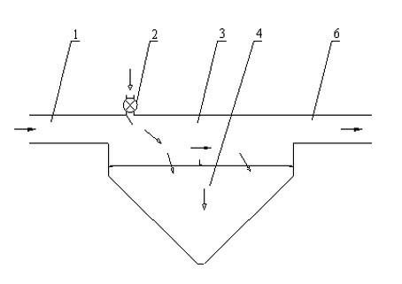
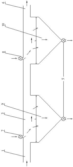
[0039] The device for heat exchange between gas and solid particles of the present invention includes at least one stage of heat exchange unit, each stage of the heat exchange unit includes an airflow channel 3, and an air inlet 1 is provided at one end of the airflow channel 3 , The other end is provided with an air outlet 6; the air flow channel 3 is arranged horizontally; at the bottom of the air flow channel 3, a settling collection hopper 4 extends downward, and the settling collection hopper 4 is in communication with the air flow channel 3; At least one feed port 2 is provided on the top of the air flow channel 3 and above the communication opening of the settling collection hopper 4 and the air flow channel 3, and the feed port 2 is located close to the settling collection hopper 4 The air inlet 1 is provided on one side; along the flow direction of the gas, the air outlet 6 of the airflow channel 3 of the previous heat exchange unit communicates with the air inlet 1 of ...


PUM


Abstract

The invention relates to a device for carrying out heat exchange between gas and solid particulate matters. The device comprises at least one level heat exchange unit. Each level heat exchange unit comprises an air flow channel; an air inlet is arranged at one end of the channel, and an air outlet is arranged at the other end of the channel; sedimentation material collection hoppers are arranged at the bottom of the air flow channel in a downward extending communication manner; at least one feeding opening is arranged at the top of the air flow channel and is located above a communicated opening of the sedimentation material collection hoppers and the air flow channel; the feeding opening is arranged near the air inlet; the air outlet of the air flow channel of a last grade of the heat exchange unit is communicated with the air inlet of the air flow channel of an adjacent heat exchange unit; the feeding opening of the last grade of the heat exchange unit is connected with the bottom of the sedimentation material collection hoppers of the adjacent heat exchange unit; a discharging opening is arranged at the bottom of each sedimentation collection hopper; a plurality of sedimentation collection hoppers are arranged in parallel between the air inlet and the air outlet of the air channel in each level heat exchange unit; and air flowing speed in the air flow channel is 0.2-1 m / s.

Description

Technical field [0001] The invention specifically relates to a device for heat exchange between gas and solid particles, which belongs to the field of industrial equipment. Background technique [0002] In industrial production, it is often necessary to exchange heat between gas and solid particles to obtain heated or cooled gas or solid particles. It is more common to use high-temperature gas to heat the powder formed by solid particles in order to increase the gas as much as possible. The contact time with the particulate matter and the use of the heat energy of the high-temperature gas as much as possible, usually make the gas flow and the powder form a reverse flow, so that the high-temperature gas and the powder can fully contact and mix, so that the heat exchange between the two is more It is sufficient to obtain a powder with a higher temperature. [0003] In the prior art, Chinese Patent CN 85109480A discloses a cement raw meal vertical cylinder preheater system, which inc...

Claims


Application Information

Patent Timeline
Patent Type & Authority Applications(China)
IPC IPC(8): F28C3/12
Inventor 卓卫民
Owner 卓卫民
Why Eureka
Try Eureka