Compaction positioning mechanism for bridge U rib assembly machine

A positioning mechanism and assembly machine technology, applied in bridges, bridge construction, erection/assembly of bridges, etc., can solve the problems of a large amount of work time, difficulty, and high consumption costs, and achieve fast and convenient operation, high work efficiency, and simple structure Effect

Inactive Publication Date: 2014-07-23
WUCHUAN HEAVY ENG +1
View PDF9 Cites 0 Cited by
  • Summary
  • Abstract
  • Description
  • Claims
  • Application Information

AI Technical Summary

Problems solved by technology

[0002] In the prior art, the positioning of the U-ribs is often fixed on multiple U-ribs with a profiling plate, and then the U-ribs and the bottom plate are pressed tightly with a puller. This purely manual operation requires U-ribs with different spacing Making a large number of profiling boards requires high work intensity and slow adjustment speed, and it is very difficult in the production process. It takes a lot of work time to adjust in place, and the consumption cost is very high.

Method used


Image

  • Compaction positioning mechanism for bridge U rib assembly machine
  • Compaction positioning mechanism for bridge U rib assembly machine

Examples


Embodiment Construction

[0016] Below the present invention will be further described in conjunction with the embodiment in the accompanying drawing:

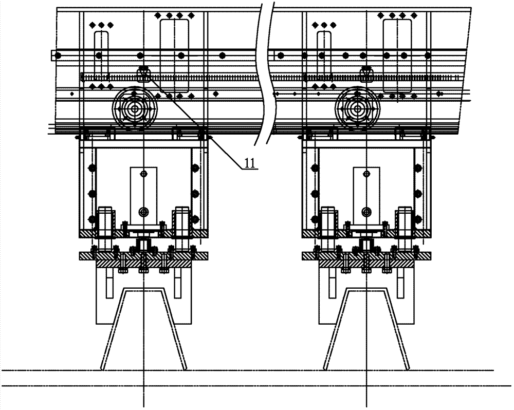
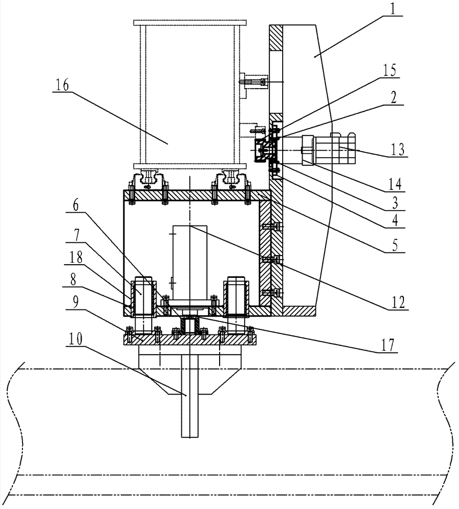
[0017] Such as Figure 1~Figure 2 As shown, the present invention mainly includes a mounting seat 1, a traverse gear 2, a mounting plate 4, a moving seat 5, a connecting seat 6, a guide rod 7, a fixed seat 9, a pressure plate 10, a hydraulic cylinder 12, a servo motor 13 and a reducer 14 .

[0018] The servo motor 13 is connected with a speed reducer 14, and the rotating shaft of the speed reducer 14 is covered with a traverse gear 2. The traverse gear 2 is engaged with the fixed rack 15 on the assembly machine 16 . The reducer 14 is installed on the mounting plate 4 , and the mounting plate 4 is mounted on the mounting seat 1 .

[0019] The lower end of the mounting base 1 is connected to the moving base 5, the upper end of the moving base 5 is installed on the assembly machine 16, and the hydraulic cylinder 12 is installed in the moving base 5. T...


PUM


Abstract

The invention relates to a compaction positioning mechanism for a bridge U rib assembly machine, which is particularly used for evenly positioning a plurality of U ribs on a bottom plate in a compacted manner in the process of assembling the U ribs with the bottom plate, and belongs to the technical field of the mechanical equipment. The compaction positioning mechanism comprises a mounting seat, a traversing gear, a mounting plate, a movable seat, a connecting seat, a guide rod, a fixed seat, a pressing plate, a hydraulic cylinder, a servo motor and a speed reducer. The compaction positioning mechanism is simple, compact and reasonable in structure, rapid and convenient in operation, high in working efficiency and low in cost, left and right positions are adjusted by driving the traversing gear to transversely move on a fixed rack through the servo motor, and the pressing plate is driven to clamp the U ribs by means of extension and retraction of the hydraulic cylinder so that the purposes of clamping and positioning are achieved.

Description

technical field [0001] The invention relates to a pressing and positioning mechanism of a bridge U-rib assembly machine, in particular, it is used in the assembly process of multiple U-ribs and the bottom plate to quickly evenly distribute and press and position multiple U-ribs on the bottom plate, belonging to Machinery and equipment technology field. Background technique [0002] In the prior art, the positioning of the U-ribs is often fixed on multiple U-ribs with a profiling plate, and then the U-ribs and the bottom plate are pressed tightly with a puller. This purely manual operation requires U-ribs with different spacing Making a large number of profiling boards requires high work intensity and slow adjustment speed, and it is very difficult in the production process. It takes a lot of work time to adjust it in place, and the consumption cost is very high. Contents of the invention [0003] The purpose of the present invention is to overcome the above-mentioned shor...

Claims


Application Information

Patent Timeline
Patent Type & Authority Patents(China)
IPC IPC(8): E01D21/00
Inventor 黄新明沈奇杨念记李秀成龚国华吴云强刘新立周洪根朱越来钱军
Owner WUCHUAN HEAVY ENG
Why Eureka
Try Eureka