
Shaft processing fixture

A technology of fixtures and shafts, which is applied in the field of mechanical processing auxiliary fixing fixtures, can solve the problems of large machining errors and difficulty in fixing workpieces, and achieve the effects of increasing the pressing area, increasing stability, and ensuring machining accuracy

Inactive Publication Date: 2012-07-25
SUZHOU TANGFENG METAL PROD
View PDF0 Cites 7 Cited by
  • Summary
  • Abstract
  • Description
  • Claims
  • Application Information

AI Technical Summary

Problems solved by technology

However, the curved surface of the workpiece makes it difficult to fix the workpiece during processing. If the clamping is not fastened, it will roll on the workbench, resulting in large machining errors.

Method used


Image

  • Shaft processing fixture
  • Shaft processing fixture
  • Shaft processing fixture

Examples


Embodiment Construction

[0016] The present invention is described below in conjunction with accompanying drawing.

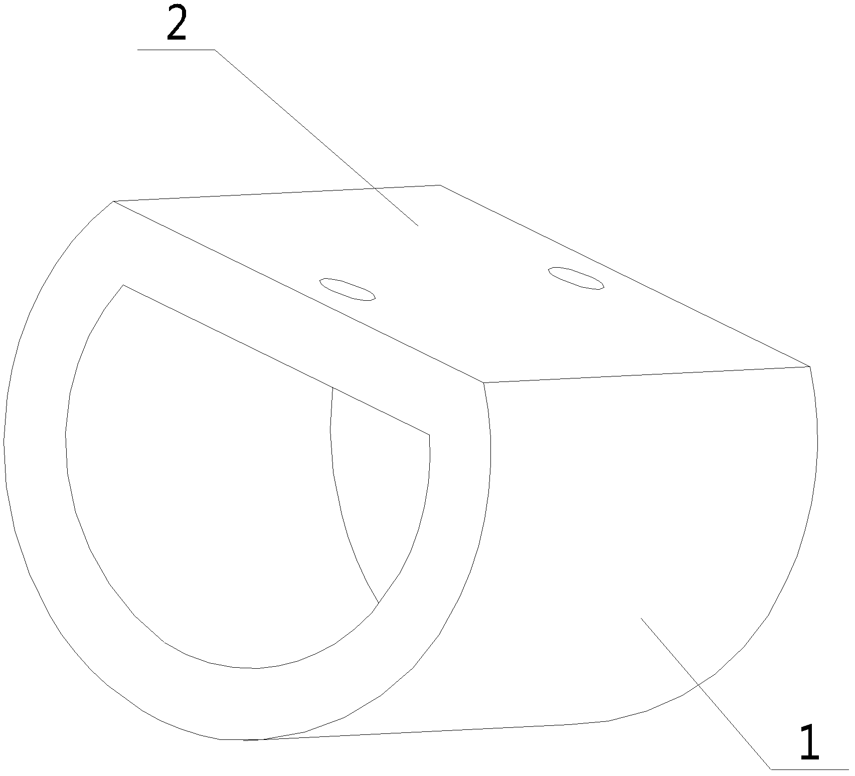
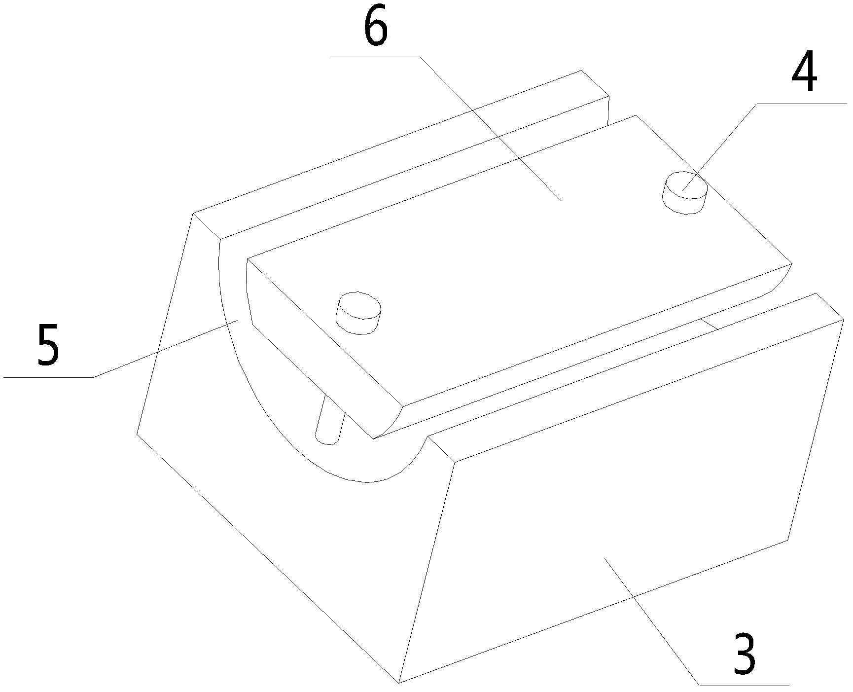
[0017] with processing attached figure 1 Take the top surface 2 of workpiece 1 shown in as an example, with Figure 2-4 It is a kind of shaft processing fixture according to the present invention, which includes a clamp body 3, a pressure block 6 and a compression bolt 4; the clamp body 3 is a cuboid, and the center of the top surface of the clamp body 3 is provided with an accommodation groove 5 The cross-section of the accommodating groove 5 is arc-shaped; the left and right sides of the briquetting block 6 in contact with the accommodating groove 5 are arc-shaped surfaces; The radians of 5 are the same; the upper and lower surfaces of the briquetting block 6 are planes, and the length of the briquetting block 6 is the same as that of the accommodating groove 5; the briquetting block 6 is located above the accommodating groove 5, and passes through the The compression bolt 4 compres...


PUM


Abstract

The invention discloses a shaft processing fixture, which comprises a fixture body, a pressing piece and holddown bolts. A holding groove is arranged in the center of the top of the fixture body, the section of the holding groove is arc-shaped, a left side surface and a right side surface, which contact with the holding groove, of the pressing piece are arc-shaped surfaces, and the pressing piece is positioned on the upper side of the holding groove and fixedly presses a workpiece into the holding groove by the aid of the holddown bolts at the front end and the rear end of the pressing piece. By the aid of the shaft processing fixture, the pressing area of the workpiece is increased, clamping stability of the workpiece is improved, and processing precision of the workpiece is guaranteed.

Description

technical field [0001] The invention relates to a jig for machining, which belongs to the technical field of auxiliary fixing jigs for machining because it is a jig for machining shaft parts. Background technique [0002] In order to assist the normal processing of mechanical parts, ensure the stability of the workpiece to be processed, and improve the processing accuracy of the workpiece, it is generally equipped with various fixed chucks and fixed fixtures. For example, when milling on a milling machine, the workpiece is generally fixed on the workbench by a vise for milling. But for some shaft workpieces, such as attached figure 1 The workpiece 1 shown in , since the shape of the workpiece is an arch formed by a circular arc surface and a plane, in the last process of processing, the top surface 2 of the workpiece must be milled or ground for finishing, and Drilling operations are carried out on this plane. The curved surface of the workpiece makes it difficult to fix ...

Claims


Application Information

Patent Timeline
Patent Type & Authority Applications(China)
IPC IPC(8): B23Q3/06
Inventor 唐剑峰
Owner SUZHOU TANGFENG METAL PROD
Learn More