
Experimental gas generating device

A gas generating device, a technology used in experiments, applied in the directions of mixers, dissolvers, mixers, etc. with rotary stirring devices

Inactive Publication Date: 2012-07-25
CLEAR ENVIRONMENT TECH SUZHOU
View PDF2 Cites 0 Cited by
  • Summary
  • Abstract
  • Description
  • Claims
  • Application Information

AI Technical Summary

Problems solved by technology

Existing organic waste gas generators usually use organic solvents dissolved in a certain amount of air, and then injected into the experimental equipment, which can provide a small experimental gas flow rate, generally tens to hundreds of milliliters per minute

Method used


Image

  • Experimental gas generating device
  • Experimental gas generating device

Examples


Embodiment Construction

[0015] The present invention will be described in further detail below through specific examples.

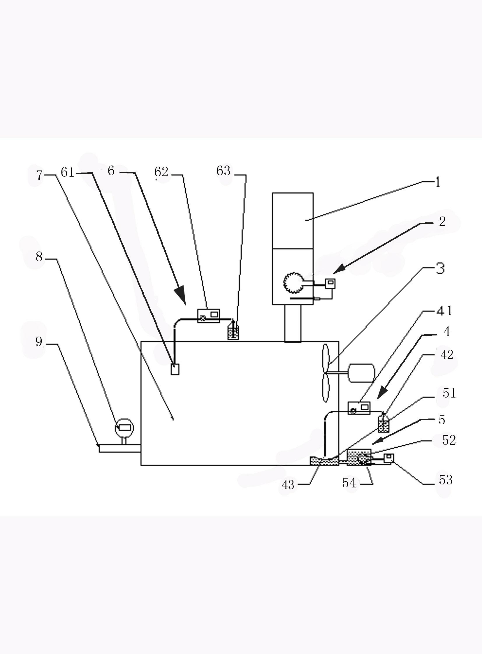
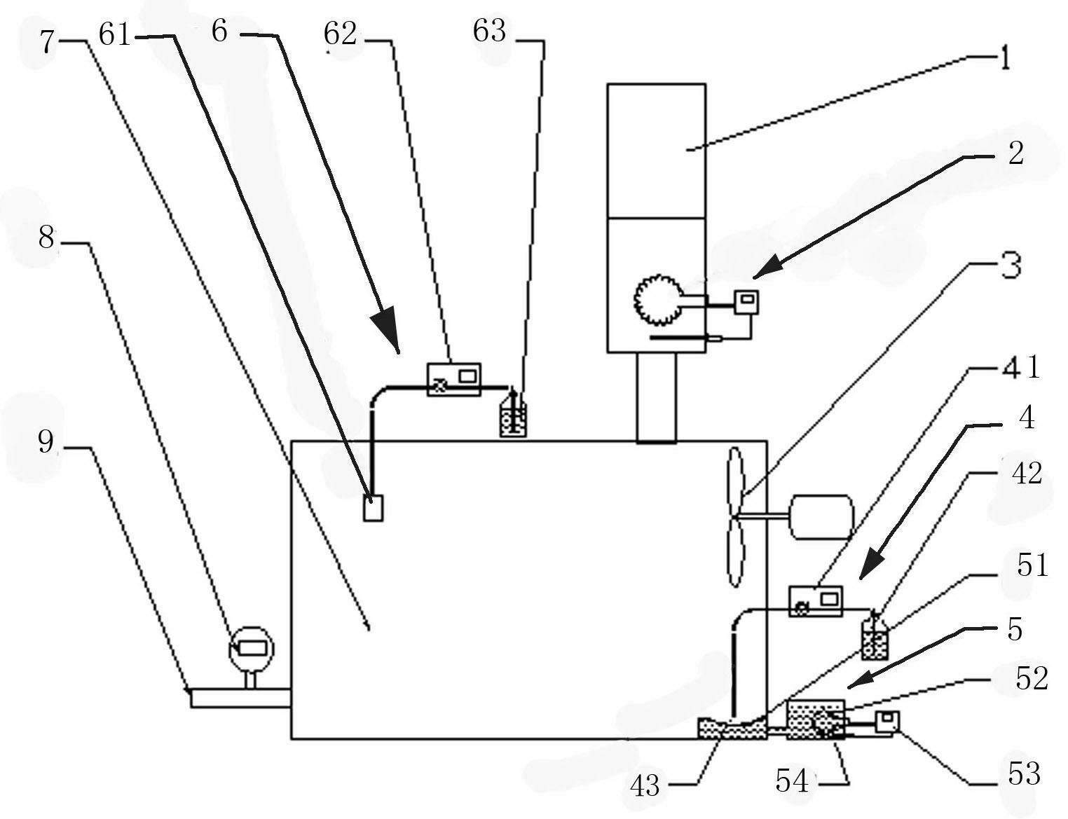
[0016] An experimental gas generating device, such as figure 1 As shown, a buffer tank 7 is included, and the buffer tank 7 is provided with an air inlet, an air outlet 9, a medicament input port and a water input port, and the air inlet is sequentially provided with an air intake purification device 1 and a water inlet along the airflow direction. Air intake heating device 2, an air flow meter 8 is installed at the air outlet 9 of the buffer tank 7, the drug input port is connected to the drug input device 4 that quantitatively inputs the drug in the buffer tank 7, and the water input port is connected with The water input device 6 quantitatively sprays water to the buffer tank 7, and the buffer tank 7 is equipped with a homogenizing fan 3, a water atomization device 61 and a drug evaporation device 5 for heating and evaporating the input drug.

[0017] The air intake purific...


PUM


Abstract

The invention discloses an experimental gas generating device, which comprises a buffer tank. The buffer tank is provided with a gas inlet, a gas outlet, a medicine input port and a water input port, a gas purification device and a gas heating device are arranged sequentially at the gas inlet along the gas flow direction, an air flow meter is arranged at the gas outlet of the buffer tank, the medicine input port is connected with a medicine input device used for quantitatively inputting medicine into the buffer tank, the water input port is connected with a water input device used for quantitatively spraying water into the buffer tank, a homogenization fan, a water atomizing device and a medicine evaporating device used for heating to evaporate the input medicine are arranged in the buffer tank. When the experimental gas generating device is used, large-flow experimental gas which complies with requirements and has controllable component stability can be provided, and the requirements of performance testing of engineering prototypes can be satisfied.

Description

technical field [0001] The invention relates to a gas generating device, in particular to an experimental gas generating device. Background technique [0002] In order to study various exhaust gas treatment technologies, it is necessary to simulate exhaust gases with different components in the laboratory for various treatment experiments. Existing organic waste gas generators usually dissolve organic solvents in a certain amount of air and then inject them into experimental equipment. The experimental gas flow rate that can be provided is relatively small, generally tens to hundreds of milliliters per minute. As for the engineering prototype of waste gas treatment equipment, in order to get as close as possible to the structure of the actual equipment, the flow rate of its waste gas treatment needs to reach hundreds of liters per minute. Therefore, it is necessary to design a new type of experimental gas generating device to meet the testing requirements of the engineering ...

Claims


Application Information

Patent Timeline
Patent Type & Authority Applications(China)
IPC IPC(8): B01F7/04B01F15/02B01F15/06B01F15/04
Inventor 张昊刁国平蒋建平
Owner CLEAR ENVIRONMENT TECH SUZHOU
Learn More