Roller conveyor and method for operating same

A conveyor and roller technology, applied in conveyors, conveyor objects, conveyor control devices, etc., can solve problems such as the height of the roller body, and achieve the effects of improving heat load, stabilizing supply voltage, and avoiding overvoltage

Active Publication Date: 2012-07-18
TGW MECHANICS GMBH
View PDF8 Cites 3 Cited by
  • Summary
  • Abstract
  • Description
  • Claims
  • Application Information

AI Technical Summary

Problems solved by technology

The frequent switching cycles of the known conveyor rollers, ie switching between driving and braking of the conveyor rollers, lead to a high temperature rise of the roller bodies

Method used


Image

  • Roller conveyor and method for operating same
  • Roller conveyor and method for operating same
  • Roller conveyor and method for operating same

Examples


Embodiment Construction

[0028] At the outset, it should be pointed out that the same reference symbols or the same component designations are used for the same components in the differently described embodiments, wherein the disclosure content contained in the entire description can be transferred to the components with the same reference symbols or the same component designations. parts. Likewise, positional indications such as top, bottom, side, etc. selected in the description relate to the currently described and illustrated figure and can be transferred to the new position as appropriate in the event of a position change.

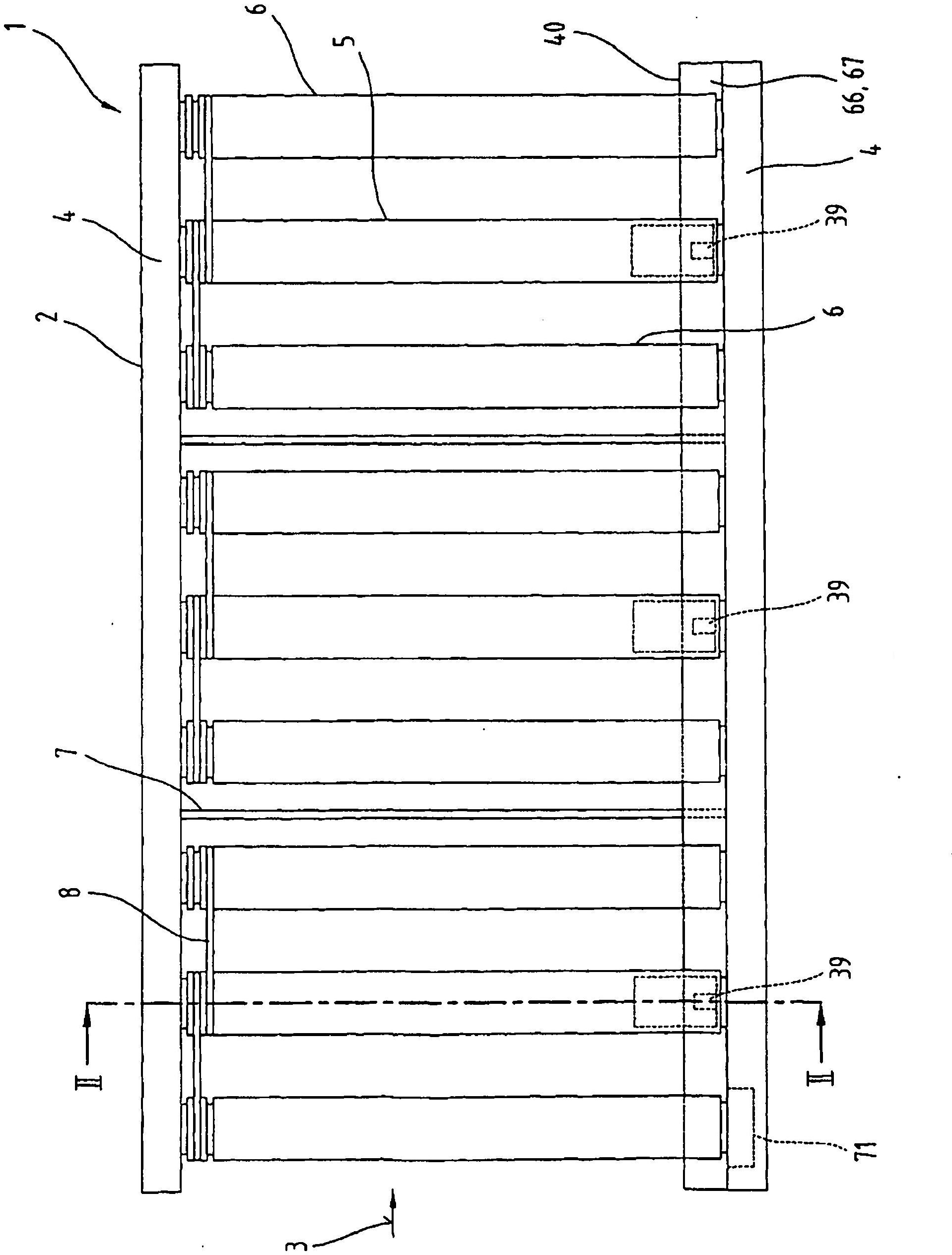
[0029] figure 1 shows a partial plan view of a conveyor system with a roller conveyor 1 for conveying loads, such as containers. The conveying device 1 comprises a frame 2 with a frame profile 4 extending parallel to the conveying direction 3 and conveying rollers 5, 6, wherein the conveying roller 5 is equipped with a motor (drive motor) which will be explained in detail fu...


PUM


Abstract

The invention relates to a roller conveyor and a method for operating same, said conveyor comprising an electrical power supply system (67, 73) and a plurality of conveyor rollers (5, 6). At least one of the conveyor rollers (5) comprises a roller element and an electrical machine arranged inside said roller element. The electrical machine of the conveyor roller (5) is supplied with electrical power by the electrical power supply system (67, 73) and produces electrical power inside said conveyor roller in the manner of a generator during the deceleration phase when a conveyed item (83) is braked. The electrical power generated by the electrical machine is fed from the conveyor roller (5) into the power supply system (67, 73) via a power supply line (74).

Description

technical field [0001] The invention relates to a roller conveyor as stated in the preambles of claims 1 and 8 and to a method of operating the same. Background technique [0002] Conveyor rollers are known which have a roller body mounted rotatably on a roller shaft and a drive motor arranged inside the roller body. Such conveyor rollers are often used in practice where the drive motor has to be protected against external influences such as dust, liquid or other dirt. The drive motor generates heat during operation. In most cases, a maximum temperature should not be exceeded according to the use temperature of the conveying rollers. [0003] In order to avoid exceeding the maximum temperature, the electric drive power of the motorized conveyor rollers can be distributed over several motorized conveyor rollers. As a result, several motorized conveyor rollers are required, which increases the wiring and connection costs of the conveyor rollers. [0004] According to US 20...

Claims


Application Information

Patent Timeline
Patent Type & Authority Applications(China)
IPC IPC(8): B65G23/08B65G43/10
CPCB65G23/08B65G43/10
Inventor C·沃尔克斯多费尔J·赖施尔
Owner TGW MECHANICS GMBH
Why Eureka
Try Eureka