Machine tool control method and control device

A technology of operating machinery and control methods, which is applied in the direction of automatic control devices, feeding devices, program control, etc., can solve the problems of cutting edge loss of processing tools, poor roughness of processing surfaces, etc., to increase processing time and improve roughness of processing surfaces degree, the effect of preventing chattering

Inactive Publication Date: 2012-07-18
MITSUBISHI HEAVY IND LTD
View PDF7 Cites 0 Cited by
  • Summary
  • Abstract
  • Description
  • Claims
  • Application Information

AI Technical Summary

Problems solved by technology

If chattering occurs, the roughness of the machined surface of the workpiece is poor, and the cutting edge of the machining tool is worn due to vibration.

Method used


Image

  • Machine tool control method and control device
  • Machine tool control method and control device
  • Machine tool control method and control device

Examples


Embodiment Construction

[0023] Hereinafter, embodiments to which the control method and control device for a working machine according to the present invention are applied will be described in detail with reference to the drawings. In addition, this invention is not limited to this embodiment.

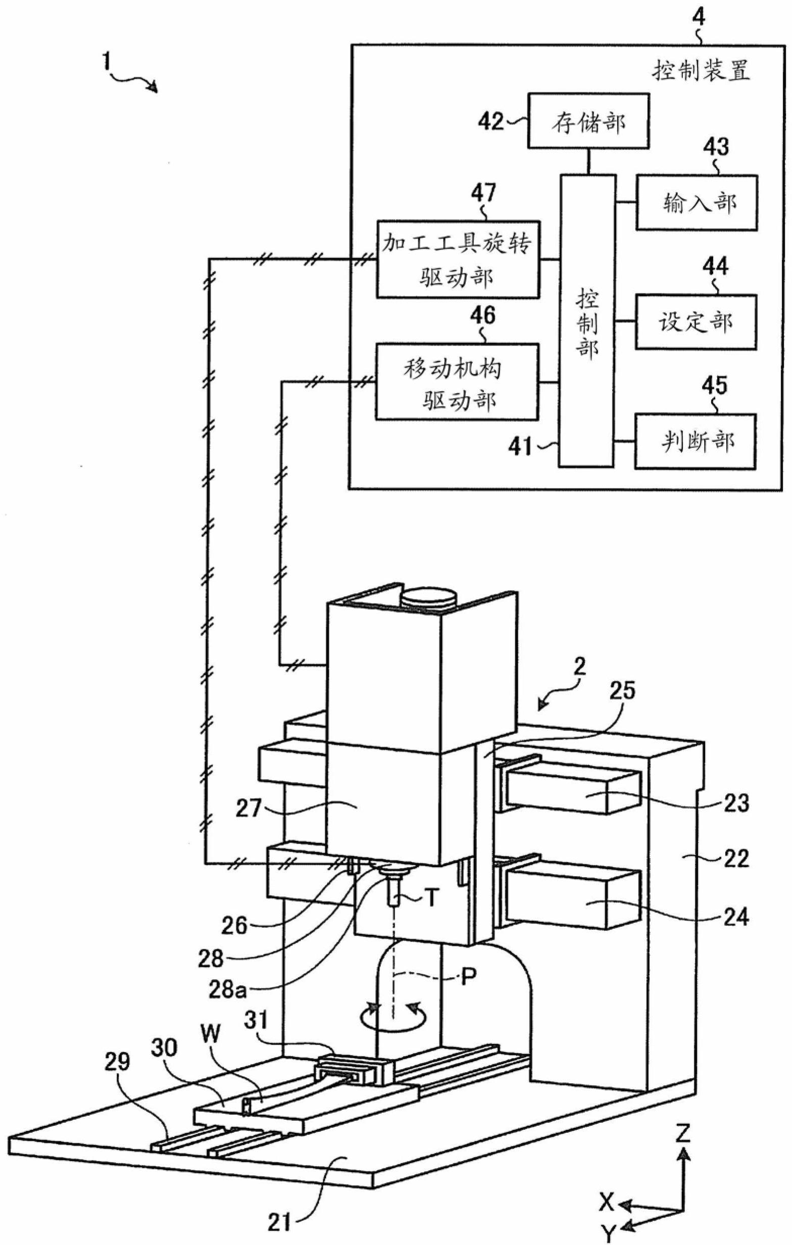
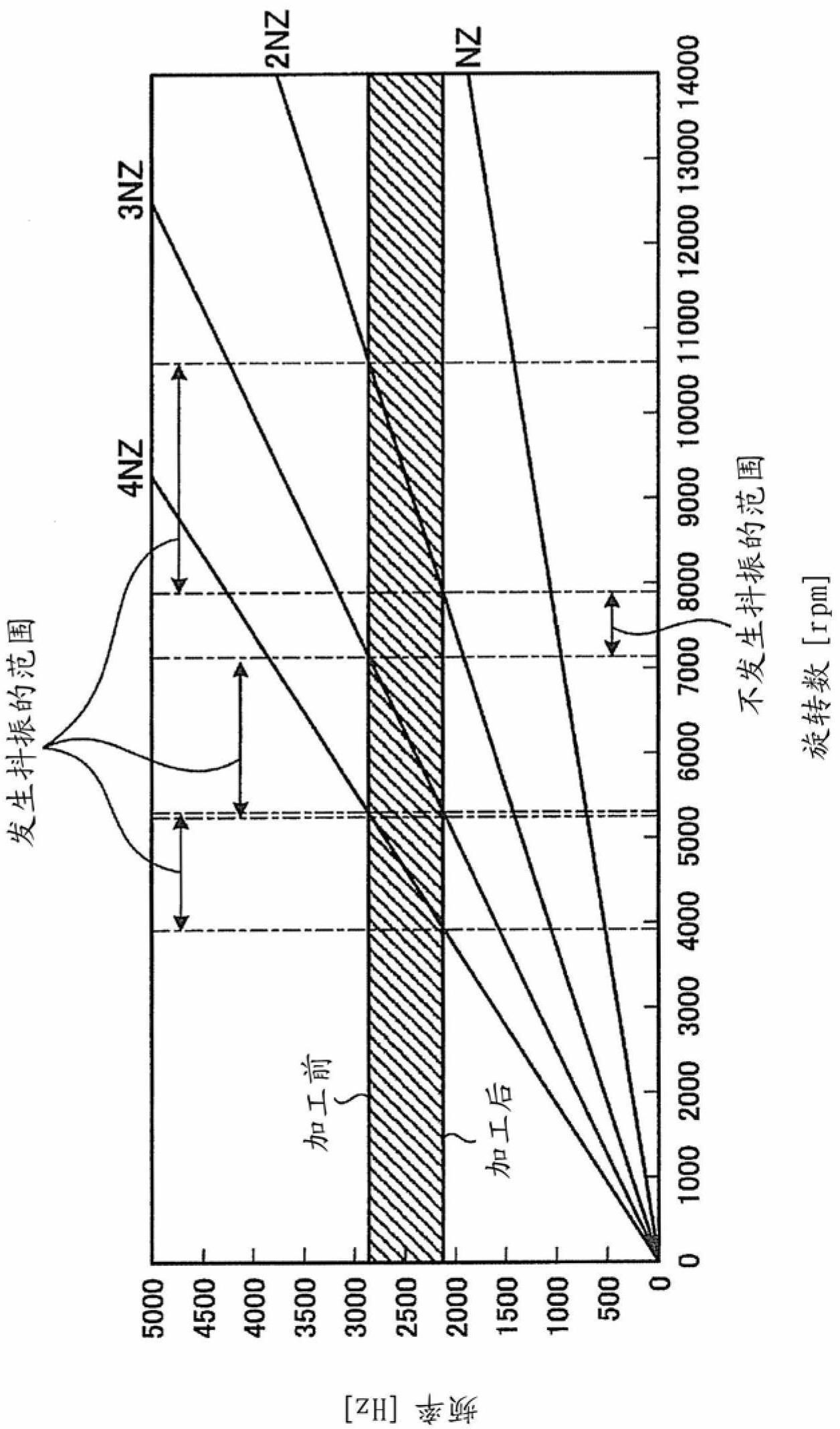
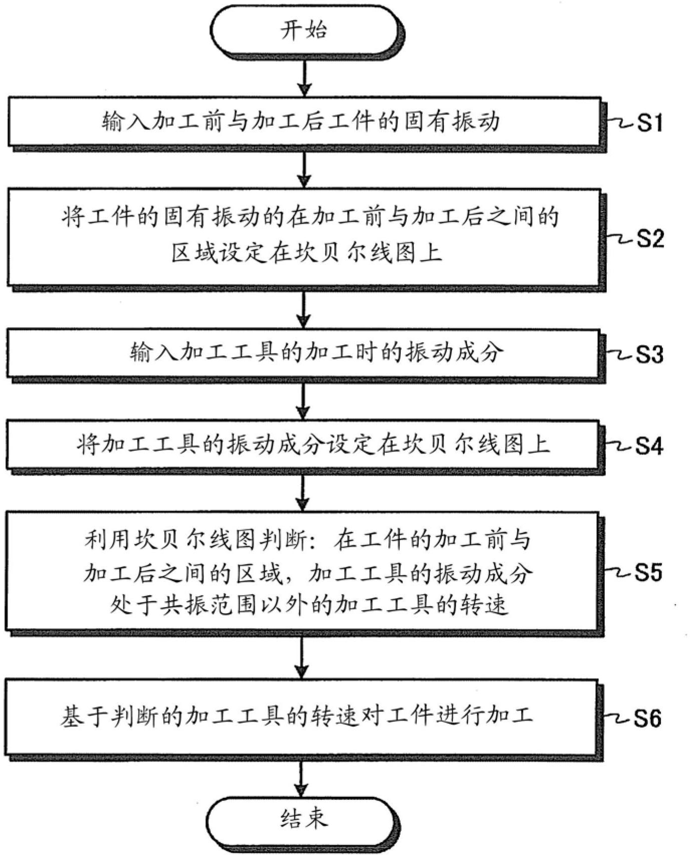
[0024] figure 1 is a schematic configuration diagram showing a working machine control device according to an embodiment of the present invention, figure 2 is a Campbell diagram for judging the working conditions of the machining tool, image 3 yes figure 1 A flow chart of the operation (control method) of the control device of the working machine is shown.

[0025] Such as figure 1 As shown, a workpiece processing device 1 as a working machine has a processing unit 2 and a control device 4 .

[0026] A base 21 is provided at the lower part of the processing part 2 . A door-shaped pillar 22 is arranged on the base 21 . A mount 25 is reciprocally supported on the front surface of the pillar 22 via guid...


PUM


Abstract

In the first place, the characteristic frequency of a workpiece before machining and the one at after machining are input (Step S1). In the next place, a region between the characteristic vibration of a workpiece before machining and the one after machining is set in a Campbell diagram (Step S2). Furthermore, the vibration components of a machining tool during machining are input (Step S3). Subsequently, the vibration components of a machining tool during machining are set in the Campbell diagram (Step S4). Thereafter, with respect to the region between the characteristic vibration of a workpiece before machining and the one after machining, the Campbell diagram is used to determine the rotational speeds (operating condition) of the machining tool outside the ranges where the vibration components of the machining tool resonate (Step S5). In the last place, workpiece machining is executed on the basis of the rotational speeds (operating condition) of the machining tool (Step S6). For this reason, the machined surface roughness of the workpiece can be improved, and the machining cost can be reduced.

Description

technical field [0001] The present invention relates to a control method and control device for an operating machine, which prevents chattering during machining of workpieces in an operating machine that performs cutting and the like. Background technique [0002] For example, in cutting machining, chattering occurs when the vibration of the machining tool resonates with the natural vibration of the workpiece. When chattering occurs, the roughness of the machined surface of the workpiece is poor and the cutting edge of the machining tool is worn due to the vibration. [0003] As a countermeasure against chattering, there is a method described in Patent Document 1, for example. In this method, the vibration data of the workpiece is obtained in the current process, and the vibration data is used to predict whether chattering will occur in the next process with higher machining accuracy. Based on the predicted chattering results, modify the following Processing data of a work...

Claims


Application Information

Patent Timeline
Patent Type & Authority Applications(China)
IPC IPC(8): B23Q15/12G05B19/18
CPCG05B2219/45147B23Q17/0976G05B2219/37435G05B2219/37434B23Q15/12G05B19/18
Inventor 安田千秋梅原隆一井上淳司清水信男松下裕一
Owner MITSUBISHI HEAVY IND LTD
Why Eureka
Try Eureka