
Pulse width modulation (PMW) rectifier control method under unbalanced power grid voltage based on power instruction compensation

A grid voltage and power compensation technology, which is applied in the direction of reducing the asymmetry of the multi-phase network, reducing harmonics/ripples in the AC network, eliminating/reducing asymmetry in the multi-phase network, etc., to achieve easy implementation, extended operating performance, and expanded good sex effect

Inactive Publication Date: 2012-07-18
NORTH CHINA UNIVERSITY OF TECHNOLOGY
View PDF3 Cites 25 Cited by
  • Summary
  • Abstract
  • Description
  • Claims
  • Application Information

AI Technical Summary

Problems solved by technology

At present, there is no better method that can simultaneously satisfy: 1) It is completely realized on the static coordinates; 2) No complex signal processing algorithms such as filters are needed; 3) It is easy to integrate with the existing PWM rectifier control method under the balanced grid

Method used


Image

  • Pulse width modulation (PMW) rectifier control method under unbalanced power grid voltage based on power instruction compensation
  • Pulse width modulation (PMW) rectifier control method under unbalanced power grid voltage based on power instruction compensation
  • Pulse width modulation (PMW) rectifier control method under unbalanced power grid voltage based on power instruction compensation

Examples


Embodiment Construction

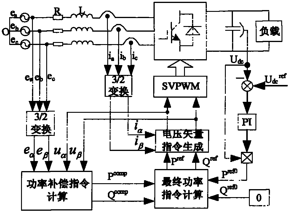
[0019] The present invention will be further described below in conjunction with the accompanying drawings, wherein the link of voltage command vector generation takes predictive direct power control as an example, but it is only used to explain the present invention, but not to limit the scope of the present invention:

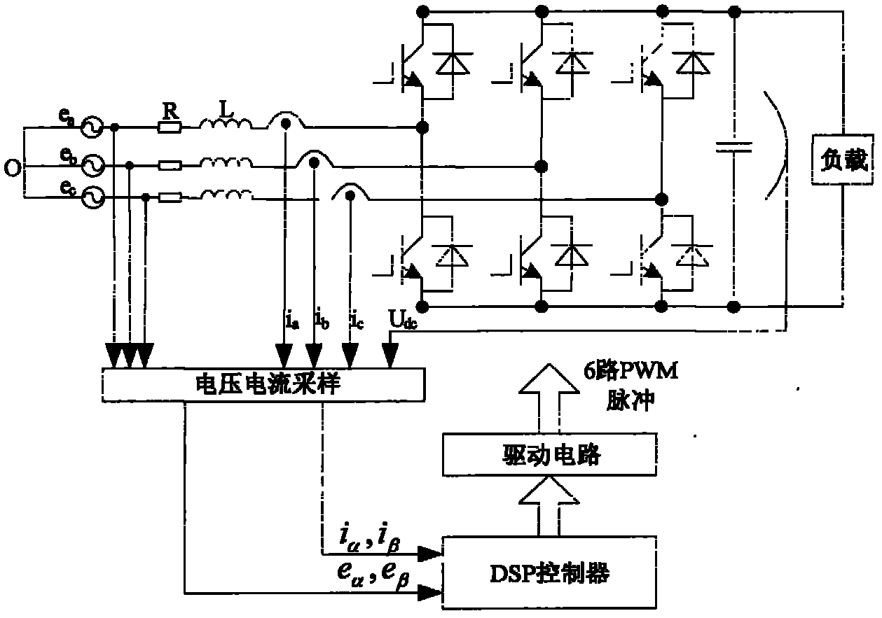
[0020] figure 1 It is a hardware circuit structure diagram of the present invention, including a three-phase voltage source, a three-phase filter inductance (R in the figure is an equivalent resistance), a rectifier bridge main circuit, a DC side capacitor, a load, a voltage and current sampling circuit, a DSP controller and a drive circuit. The voltage and current sampling circuit uses the voltage Hall sensor and the current Hall sensor to collect the three-phase network side AC voltage, AC current and rectifier DC side voltage respectively, and enters the DSP controller after the signal conditioning circuit to convert it into a digital signal. The DSP cont...


PUM


Abstract

The invention relates to a three phase PMW rectifier control technology under unbalanced power grid voltage and belongs to the power electronic technology field. Active power and reactive power given compensation values are obtained under a static coordinate through rectifier direct current side voltage, power grid voltage and power grid current, and using rectifier alternating current side voltage and power grid voltage, and delayed signals of the rectifier alternating current side voltage and power grid voltage. The compensation values plus original power given values on the basis of balanced power grid voltage serve as final power given values, then instruction values of the rectifier alternating current side voltage are obtained by using predicting direct power control method, and driving signals controlled by six switches are obtained through the decomposition of a space vector pulse width modulation (SVPMW). The method does not need the change of coordinate rotation, and is easy to be integrated into the existing control method under balanced power grid voltage. The method has the advantages of being small in computation, easy to achieve, good in robustness and the like, and can reduce the harmonic distortion of grid side currents while eliminating direct current voltage ripples.

Description

technical field [0001] The invention relates to a control method of a three-phase voltage type PWM rectifier, in particular to a control method of a PWM rectifier under unbalanced grid voltage, and belongs to the technical field of power electronics. Background technique [0002] The actual grid voltage is usually unbalanced, including amplitude unbalance and phase unbalance. When the PWM rectifier is controlled according to the control strategy under ideal balanced grid conditions, a large number of harmonics will appear in the grid-side current, and the output voltage of the DC side will fluctuate, which will affect the system performance. For this reason, scholars from all over the world have studied the PWM rectifier control under unbalanced grid voltage, in order to achieve a constant DC voltage output, reduce the harmonics of the grid-side current, and keep the average power factor of the grid side as zero as possible. In the existing methods, such as "Dual current co...

Claims


Application Information

Patent Timeline
Patent Type & Authority Applications(China)
IPC IPC(8): H02J3/26H02J3/01
CPCY02E40/50Y02E40/40
Inventor 张永昌李正熙
Owner NORTH CHINA UNIVERSITY OF TECHNOLOGY
Learn More