
Cam-type disc clamping device

A clamping device and disc-shaped technology, applied in the direction of electrical components, semiconductor/solid-state device manufacturing, circuits, etc., to achieve the effects of avoiding flying out, easy to implement, and strong wear resistance

Inactive Publication Date: 2012-07-18
北京硅元科电微电子技术有限责任公司
View PDF3 Cites 3 Cited by
  • Summary
  • Abstract
  • Description
  • Claims
  • Application Information

AI Technical Summary

Problems solved by technology

[0005] The technical problem to be solved by the present invention is how to realize the clamping of discs conveniently and simply without complicated structures and expensive parts

Method used


Image

  • Cam-type disc clamping device
  • Cam-type disc clamping device
  • Cam-type disc clamping device

Examples


Embodiment Construction

[0034] The specific implementation manners of the present invention will be further described in detail below in conjunction with the accompanying drawings and embodiments. The following examples are used to illustrate the present invention, but are not intended to limit the scope of the present invention.

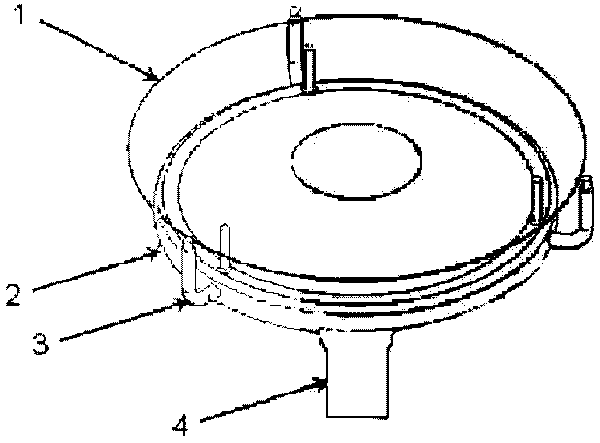
[0035] Such as Figure 1-Figure 6 As shown, it is a schematic structural diagram of a cam-type disk clamping device provided by an embodiment of the present invention, which includes a chuck 2 , a clamping mechanism 3 and a cam 4 .

[0036] Wherein the chuck 2 is a circular disc, which can rotate under the drive of a driving device such as a motor, and a cam 4 is installed at the center of the lower part thereof.

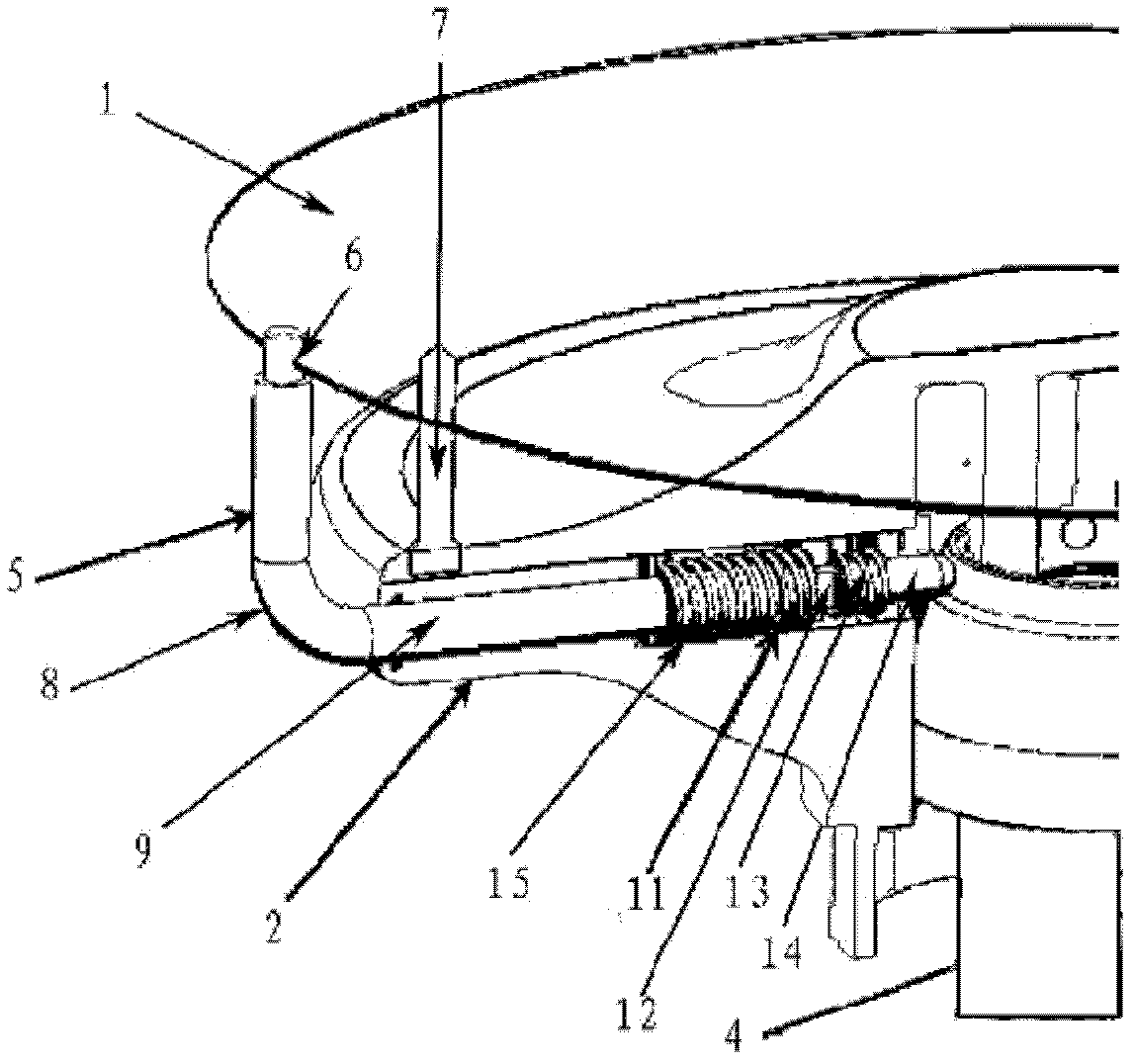
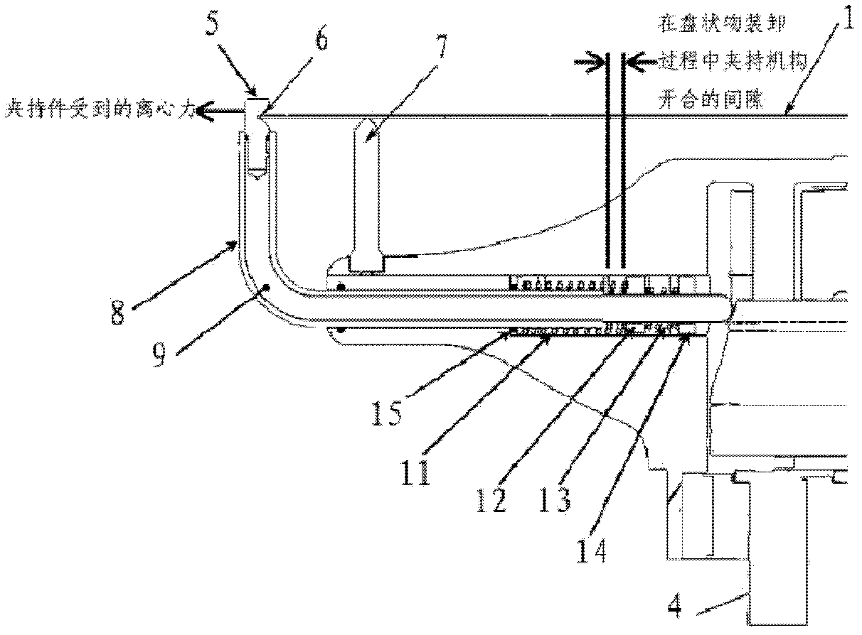
[0037] The clamping mechanism 3 includes a clamping piece 5 and an extension rod 9 . The extension rod 9 is L-shaped, one end of which is detachably connected with the clamping member 5, and faces upwards, and the other end extends into the interior of the chu...


PUM


Abstract

The invention relates to the technical field of integrated circuits, and in particular discloses a cam-type disc clamping device. The cam-type disc clamping device comprises a cam, a clamp disc and clamping mechanisms, wherein the centre on the lower part of the clamping disc is connected with the cam; the clamping mechanisms are all arranged on the clamping disc; and each clamping mechanism comprises an extension rod, wherein one end of the extension rod is extended into the clamping disc and is contacted with the circumference of the cam, and the other end of the extension rod is upward and is provided with a clamping piece used for clamping a disc object. By using the device, the disc object can be clamped conveniently and rapidly; and moreover, the device is simple in structure, low in cost and easy to implement.

Description

technical field [0001] The invention relates to the technical field of integrated circuits, in particular to a cam-type disc clamping device. Background technique [0002] In the production process of integrated circuits, clamping discs, such as wafers and silicon wafers, is an important link in each production stage. Traditional methods mostly use complex mechanical linkages to grip and move the grippers. The three most important phases of fixing the clamp include: loading the disc, when the clamp is open; rotating the disc, when the clamp is clamping the disc; unloading the disc, At this moment, the clamping part is in the open state. This more traditional method of clamping a disc typically relies on many moving parts to contact the disc on the outside of the chuck, but creates many particles as the chuck rotates and when the disc is removed from the clamp, Particles can contaminate the disc. [0003] Traditional methods of fixing the disc in some cases are usually do...

Claims


Application Information

Patent Timeline
Patent Type & Authority Applications(China)
IPC IPC(8): H01L21/687H01L21/683
Inventor 凯里・雷贾星杰吴仪王波雷张豹
Owner 北京硅元科电微电子技术有限责任公司
Learn More