
Parameter curve cutter path oriented numerical control system contour error control method

A contour error and tool path technology, applied in the field of error compensation control, can solve the problems of large amount of calculation, difficult to set PID controller control parameters, difficult to meet the real-time requirements of CNC system, etc., to achieve simple calculation method and high calculation accuracy. Effect

Inactive Publication Date: 2012-07-18
SHANDONG UNIV OF TECH
View PDF3 Cites 39 Cited by
  • Summary
  • Abstract
  • Description
  • Claims
  • Application Information

AI Technical Summary

Problems solved by technology

The problem with this method is that the Newton iterative method has high requirements for the initial value and a large amount of calculation, and sometimes it is difficult to meet the real-time requirements of the numerical control system.
Myung-Hoon LEE also proposed in this paper that in addition to the following error PID position controller of each axis, for the contour error obtained by approximate calculation, another set of PID controller is designed to calculate the contour error compensation, but the control parameters of the PID controller are very small. Difficult to tune

Method used


Image

  • Parameter curve cutter path oriented numerical control system contour error control method
  • Parameter curve cutter path oriented numerical control system contour error control method
  • Parameter curve cutter path oriented numerical control system contour error control method

Examples


Embodiment Construction

[0017] Combine below Figure 1~3 The present invention is described in further detail:

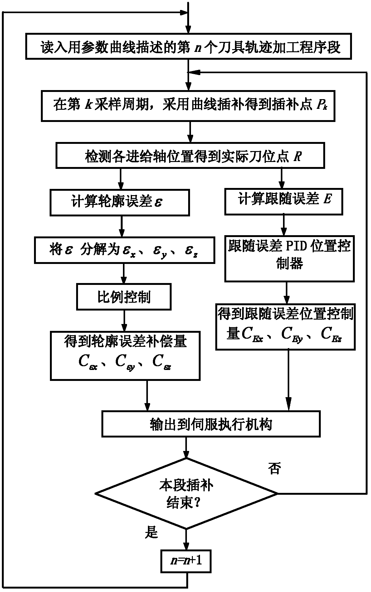
[0018] Step 1), in each sampling cycle of curve interpolation processing on the parameter curve tool trajectory, calculate the contour error according to the current actual tool position point and the interpolation point on the tracked parameter curve tool trajectory, that is, calculate the current actual tool position The shortest distance from the point to the tracked parametric curve toolpath. Specific as figure 2 As shown, suppose the tool path L is described by a NURBS parameter curve, and each point on the tool path L is

[0019] P ( u ) = Σ i = 0 n B i , k ...


PUM


Abstract

The invention provides a parameter curve cutter path oriented numerical control system contour error control method which comprises the following steps of: 1) calculation of the contour error; 2) calculation and control of the contour error compensation quantity, and is characterized in that: in the step 1), in each sampling period for performing curve interpolation on the parameter curve cutter path, the contour error epsilon is calculated according to the current actual cutter location point and the interpolation point on the tracked parameter curve cutter path, namely the shortest distancefrom the current actual cutter location point to the tracked parameter curve cutter path is calculated; in the step 2), the components of the contour error epsilon along the X axis, Y axis and Z axisare calculated, and the contour error compensation quantities are obtained by proportional control and superposed with the location control quantities for the following error on the X axis, Y axis and Z axis respectively; and then the result is output to a servo execution mechanism to perform contour error compensation control. The method provided by the invention has the advantages that: the contour error calculation precision is high, the contour error compensation method is simple and effective, and the contour precision can be obviously improved.

Description

technical field [0001] The invention relates to an error compensation control method, in particular to a contour error control method of a numerical control system oriented to a parameter curve tool trajectory. Background technique [0002] In the machinery manufacturing industry, the contours of many complex parts can be described by parametric curves (such as spline curves, Bezier curves, B-spline curves, NURBS curves, etc.), and correspondingly, parameter curves can be used to describe the tool paths for processing these parts . For the parameter curve tool path, the advanced CNC system mostly adopts the curve interpolation method. Compared with using a straight line segment to approach the parameter curve tool path and then performing linear interpolation, when using the curve interpolation method, all interpolation points are on the parameter curve tool path, and theoretically, the machining accuracy and processing speed can be improved at the same time. On the other ...

Claims


Application Information

Patent Timeline
IPC IPC(8): G05B19/406
Inventor 赵国勇赵玉刚王士军申永
Owner SHANDONG UNIV OF TECH
Learn More