
Multi-extreme-working-condition erosion test device applicable to multi-field coupling condition

A technology of extreme working conditions and test equipment, which is applied in the direction of measuring equipment, testing wear resistance, instruments, etc., can solve the problems such as the difficulty in the universality of erosion tests, the inability to realize the coupling verification of multiple working conditions, and the single function. To achieve the effect of authentic and reliable experimental test results

Active Publication Date: 2012-07-18
HARBIN ENG UNIV
View PDF6 Cites 30 Cited by
  • Summary
  • Abstract
  • Description
  • Claims
  • Application Information

AI Technical Summary

Problems solved by technology

Due to the ever-changing shape and temperature of the erosion fluid, it is difficult for the general erosion test equipment to have the universality of the erosion test.
Therefore, it is necessary to invent an erosion device that can more realistically simulate various extreme working conditions involved in materials in actual industrial production, so as to realize the laboratory simulation of complex service environments and the effective evaluation of the performance of service materials. For this type of service The design, development and reliability evaluation of materials in the environment are of great significance. At present, most of the research on such test devices under various extreme working conditions is in the exploratory stage or the function is relatively single, and it is impossible to realize the coupling verification of multiple working conditions.

Method used

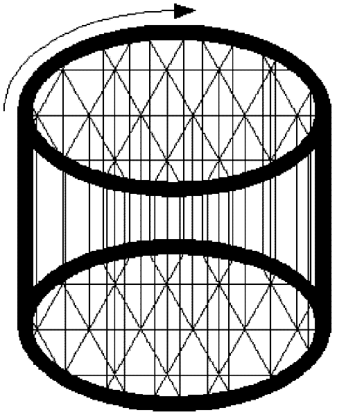

Image

  • Multi-extreme-working-condition erosion test device applicable to multi-field coupling condition
  • Multi-extreme-working-condition erosion test device applicable to multi-field coupling condition
  • Multi-extreme-working-condition erosion test device applicable to multi-field coupling condition

Examples


Embodiment Construction

[0022] The present invention is described in more detail below in conjunction with accompanying drawing example:

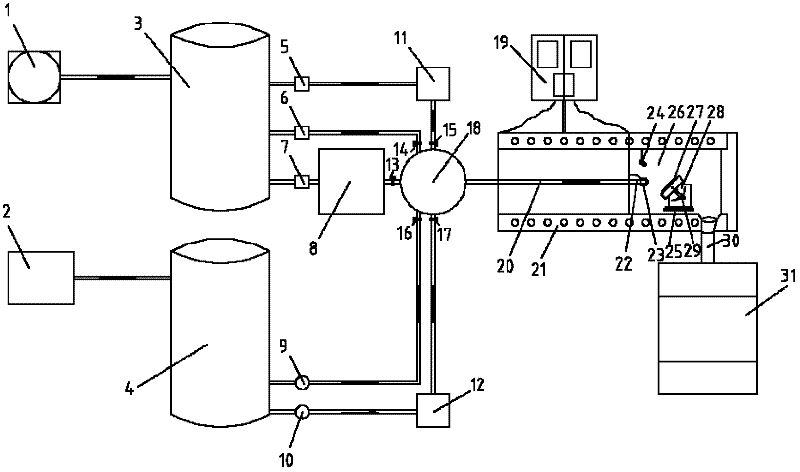
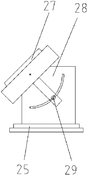
[0023] combine Figure 1-Figure 3 . The multi-extreme working condition erosion test device applicable to multi-field coupling conditions of the present invention is composed of an intake system 1, a booster system 2, a high-pressure gas storage tank 3, a sealed liquid storage tank 4, and a pressure regulation controller 5-7 , Fog making system 8, Flow regulating controller 9-10, Adding device 11-12, Valve 13-17, Mixing device 18, Heating temperature control panel 19, Erosion fluid preheating pipe 20, Heating device 21, Erosion Test nozzle 22, thermocouple 23, high temperature camera 24, high temperature electronic balance 25, erosion laboratory 26, sample to be tested 27, test bench 28, positioning nut 29, erosion fluid overflow pipe 30, erosion fluid cooling Recovery device 31 and cooperate some pipelines and fittings to form. The gas in the high-pressure gas...


PUM


Abstract

The invention relates to a multi-extreme-working-condition erosion test device applicable to multi-field coupling condition. The multi-extreme-working-condition erosion test device comprises a high-pressure gas storage tank, a sealing liquid storage tank, a mixing device, an erosion fluid preheating pipe, an erosion test room and a test platform, wherein the test platform is arranged in the erosion room; a sample to be tested is arranged on the test platform; the erosion fluid preheating pipe extends into the erosion test room and is connected with an erosion test spraying pipe; an outlet of the erosion test spraying pipe is aligned to the sample to be tested, and an inlet of the erosion test spraying pipe is connected with the mixing device; the high-pressure gas storage tank and the sealing liquid storage tank are respectively connected with the mixing device; the high-pressure gas storage tank is provided with a gas feeding system; and the sealing liquid storage tank is provided with a supercharging system. The multi-extreme-working-condition erosion test device has the advantages that multiple erosion experiment accessories are integrated and coupled scientifically, so that the effective simulation on multiple extreme conditions in the industry is realized under the laboratory condition, the test result of the experiment is more real and reliable, and simultaneously, the application and simulation in more industrial fields are realized.

Description

technical field [0001] The invention relates to a test device for testing the erosion performance of service materials in harsh environments, specifically an erosion test device that integrates multiple extreme working conditions. Background technique [0002] In various industrial equipment, such as equipment in the nuclear power industry is eroded by high-temperature fluid; equipment in the petrochemical industry is often eroded by corrosive fluid; and equipment in the aerospace industry is eroded by high-temperature gas-solid fluid Lord, wait. Due to the ever-changing shape and temperature of the erosion fluid, it is difficult for the general erosion test equipment to have the universality of the erosion test. Therefore, it is necessary to invent an erosion device that can more realistically simulate various extreme working conditions involved in materials in actual industrial production, so as to realize the laboratory simulation of complex service environments and the ...

Claims


Application Information

Patent Timeline
IPC IPC(8): G01N3/56G01N3/02
Inventor 金国崔秀芳钟景高刘金娜郭天师
Owner HARBIN ENG UNIV
Learn More