Device for acquiring multispectral microscopic image
A multi-spectral image acquisition device technology, applied in the field of multi-spectral microscopic image acquisition devices, can solve the problems of reduced spatial resolution, inability to replace at will, and poor scalability, and achieve good scalability, easy implementation, and wavelength replaceable effect
- Summary
- Abstract
- Description
- Claims
- Application Information
AI Technical Summary
Problems solved by technology
Method used
Image
Examples
Embodiment 1
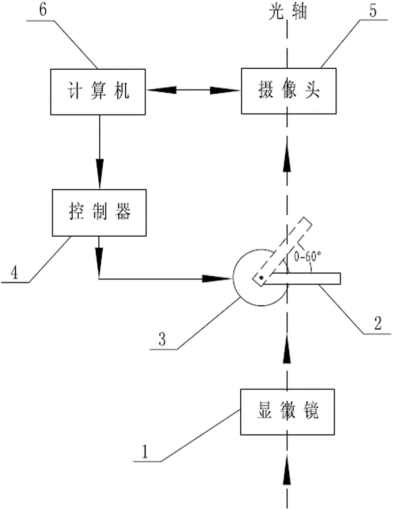
[0021] Such as figure 1 As shown, a multi-spectral image acquisition device includes a computer 6, a microscope 1, a camera 5, and an adjustable band-pass filter 2, and the microscope 1, camera 5, and adjustable band-pass filter 2 are the same Optical axis setting; the adjustable bandpass filter 2 is installed between the microscope 1 and the camera 5, and fixed on the motor 3, and the angle between the adjustable bandpass filter 2 and the optical axis is changed under the drive of the motor 3, that is, the incident The motor 3 is electrically connected to the controller 4, the controller 4 and the camera 5 are electrically connected to the computer 6, and the computer 6 controls the synchronous work of the camera 5 and the motor 3.
[0022] The image of the section enlarged by the microscope 1 is filtered by the adjustable bandpass filter 2, and only a specific spectral image is imaged on the camera 5, and the image data of a certain band can be obtained by collecting the sig...
Embodiment 2
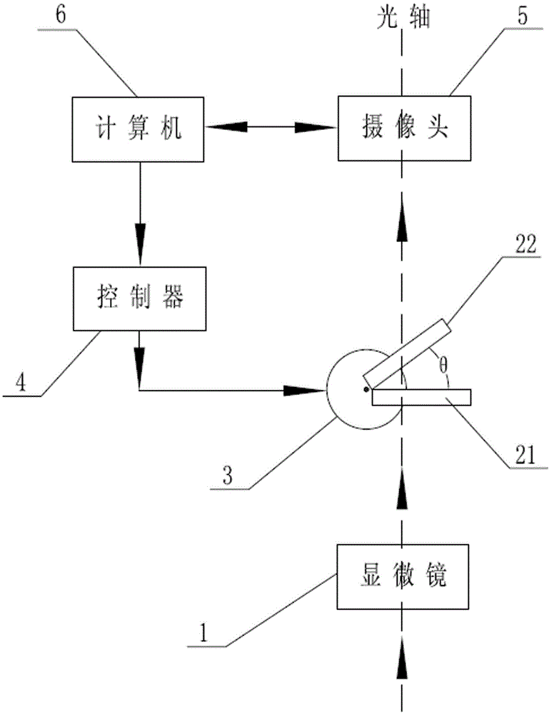
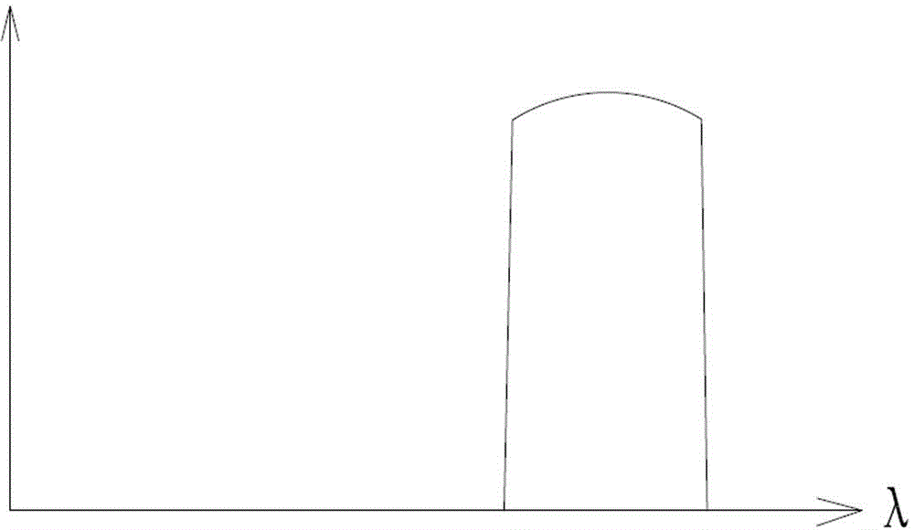
[0025] Such as figure 2 , 3 , 4, and 5, in order to obtain a narrower spectrum, two identical adjustable bandpass filters 21 and 22 can be placed and fixed at a certain angle θ, and used as a whole. In this way, the adjustable bandpass filter 21 and the adjustable bandpass filter 22 have certain deviations in the spectral curves transmitted respectively due to the existence of the included angle θ, as shown in image 3 and Figure 4 As shown, the overlapping part is the combined bandwidth, which is narrower than a single adjustable bandpass filter 21 or 22, such as Figure 5 The shaded portion shown. The combined bandwidth depends on the included angle θ. The larger θ is, the narrower the bandwidth is, but it cannot be too large, otherwise the spectral curves of the two adjustable bandpass filters 21 and 22 will not overlap and all cut off. Other parts are the same as in Embodiment 1.
PUM
 Abstract
Description
Claims
Application Information
 - R&D
- Intellectual Property
- Life Sciences
- Materials
- Tech Scout
- Unparalleled Data Quality
- Higher Quality Content
- 60% Fewer Hallucinations
Browse by: Latest US Patents, China's latest patents, Technical Efficacy Thesaurus, Application Domain, Technology Topic, Popular Technical Reports.
© 2025 PatSnap. All rights reserved.Legal|Privacy policy|Modern Slavery Act Transparency Statement|Sitemap|About US| Contact US: help@patsnap.com


