
Maintenance method for frame roller of roughing mill

A technology of rack rolls and rough rolling mills, which is applied in the direction of metal rolling racks, metal rolling mill stands, metal rolling, etc., and can solve problems such as inability to replace first and then overhaul, inconvenient on-site maintenance, and long maintenance shutdown time. Achieve the effect of convenient and fast disassembly and hoisting process, reduce online maintenance time, and reduce labor intensity

Active Publication Date: 2012-07-18
CHONGQING IRON & STEEL CO LTD
View PDF0 Cites 5 Cited by
  • Summary
  • Abstract
  • Description
  • Claims
  • Application Information

AI Technical Summary

Problems solved by technology

The rack rolls are assembled in the rough rolling mill archway, and the on-site inspection space is relatively narrow, and the largest inspection space is only about 680mm
Therefore, on-site maintenance is inconvenient, which will lead to a long maintenance shutdown time and affect production
At the same time, the irregular shape of the guide mechanism also causes the hoisting device (referring to the guide on the roughing mill) to only lift the dismantled rack rolls together with the guide mechanism to a short height, and cannot be directly lifted away from the site for maintenance; Therefore, the method of replacing first and then overhauling cannot be adopted.

Method used


Image

  • Maintenance method for frame roller of roughing mill
  • Maintenance method for frame roller of roughing mill

Examples


Embodiment Construction

[0026] The present invention will be further described in detail below in conjunction with the accompanying drawings and specific embodiments.

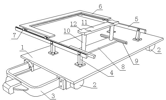
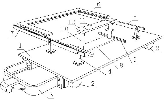
[0027] A method for overhauling a roughing mill stand roll adopts the following figure 1 Roughing mill stand roll overhaul tooling with the structure shown, including

[0028] A push-pull trolley, the push-pull trolley includes a rectangular parallelepiped plate-shaped vehicle frame 1 and a wheel 2 positioned below the vehicle frame 1, and the wheel 2 matches the work roll change track of the roughing mill;

[0029] A roll change hook 3, the roll change hook 3 is a "U" shape with two joint ends, and the joint end of the roll change hook 3 is detachably connected to one end of the push-pull trolley frame 1 in the length direction through bolts;

[0030] The roller-changing track mechanism includes two rows of columns 4 arranged along the width direction of the vehicle frame, two in each row, and the two rows of columns are opposite al...


PUM


Abstract

The invention discloses a maintenance method for a frame roller of a roughing mill, which uses a roughing mill frame roller maintenance fixture which comprises a push-pull trolley, a roller replacing hook, a roller replacing rail mechanism, a transverse moving trolley, a lifting device and the like. The maintenance method includes: integrally demounting the frame roller before lifting, erecting arail of the roller replacing rail mechanism below a frame roller mounting position, pushing the transverse moving trolley right below the frame roller, descending the frame roller on the transverse moving trolley, pulling out the frame roller along the roller replacing rail mechanism to a position above the transverse moving trolley, and using the lifting device for lifting before rotating at a certain angle, so that the push-pull trolley can be pulled out of a roughing mill gateway for maintenance and replacement. Using the maintenance method can realize demounting and lifting of the roughing mill frame roller, enable the demounting and lifting process to be convenient and quick, increase maintenance speed and reduce labor intensity. Therefore, continuity, high efficiency, stability and smoothness of hot rolling production can be guaranteed, high efficiency, orderliness and high quality of maintenance can be guaranteed, and online maintenance time for the frame roller is shortened.

Description

technical field [0001] The invention relates to a stand roll of a rough rolling mill, in particular to a method for overhauling a stand roll of a rough rolling mill. [0002] Background technique [0003] In the rolling mill, the roughing mill is the equipment used to roll the continuous cast slab to the required thickness of the intermediate slab. The stand rolls of the roughing mill are installed at the entrance and exit of the roughing mill, one for each to assist the work of the rolling mill. When working, together with the front and rear working roller tables of the rolling mill, the steel billet is sent into the gap between the upper and lower working rolls that rotate relatively for rolling. Due to the harsh working environment of the rack rolls, long-term work in the environment of high temperature of about 1100°C and high-pressure dephosphorization water of 16MPa, the high temperature and water vapor erosion can easily lead to damage to the rack rolls, especially ...

Claims


Application Information

Patent Timeline
IPC IPC(8): B21B31/12
Inventor 徐安强陈东升彭元兵柳岸伍宏
Owner CHONGQING IRON & STEEL CO LTD
Learn More