
Onboard efficient cotton cleaning device

A high-efficiency and cotton-cleaning technology, which is applied in the direction of picking machines, harvesters, agricultural machinery and implements, etc., can solve the problems of increasing the trash content, incomplete separation of seed cotton, and affecting the separation of fine trash, so as to improve the separation effect of fine trash, The effect of reducing the impurity content of seed cotton and enhancing the cleaning effect

Active Publication Date: 2012-07-18
NANJING AGRI MECHANIZATION INST MIN OF AGRI
View PDF5 Cites 16 Cited by
  • Summary
  • Abstract
  • Description
  • Claims
  • Application Information

AI Technical Summary

Problems solved by technology

The main problems are: 1) The separation of seed cotton in the upper part of the trash removal device is not complete, and the seed cotton is easily discharged directly from the trash discharge port, which will block the trash discharge port while causing cotton loss, affecting the separation of fine trash and increasing the trash content; 2. ) Part of the cotton branches directly enter the cotton collecting box without being cleaned by the second-level toothed roller; 3) There are defects in the setting of the two-level sawtooth roller, which may easily cause the cotton to be repeatedly hooked and pulled to form broken flowers; these problems lead to the existing cotton after cleaning. High impurity rate

Method used


Image

  • Onboard efficient cotton cleaning device
  • Onboard efficient cotton cleaning device
  • Onboard efficient cotton cleaning device

Examples


Embodiment 1

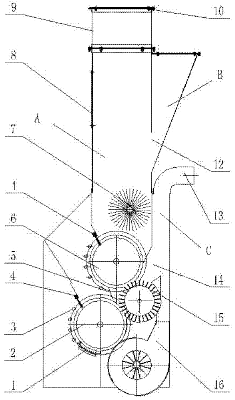
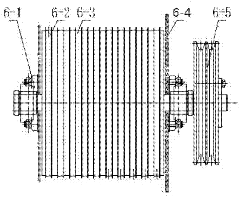
[0021] The basic structure of the airborne high-efficiency cleaning device of the present embodiment is as follows: figure 1 As shown, there is an input port 8 in the middle of one side of the vertical flow channel A at the top of the device, and the top of the vertical flow channel A is equipped with a honeycomb box 9 with honeycomb holes on the side wall, and the top of the honeycomb box 9 is equipped with a baffle. Cotton grid10. The lower part of the vertical flow channel A is equipped with parallel upper-stage toothed rollers 6 and lower-stage toothed rollers 2 supported in the lower casing. The upper brush and the lower brush 4 radially extending towards the upper toothed roller 6 and the lower toothed roller 2 are respectively installed on the lower end of the vertical channel A and the same side of the input port and the lower casing. Hairbrush 4 forms the inclination angle of about 60 ° (50 °-70 ° all can) with horizontal plane. On the side of the upper toothed roll...


PUM


Abstract

The invention relates to an onboard efficient cotton cleaning device, which belongs to the technical field of agricultural machinery and comprises a vertical flow channel with an input hole in the middle of one side. A cellular box with honeycomb holes on the lateral wall is installed on the top of the vertical flow channel, an upper toothed roller and a lower toothed roller supported inside a lower casing are installed on the lower portion of the vertical flow channel, an upper brush and a lower brush radially extending towards the upper toothed roller and the lower toothed roller are respectively mounted at the same-side lower ends of the vertical flow channel and the input hole and on the lower casing, beating rods are distributed at intervals on the sides, corresponding to the input hole, of the upper toothed roller and the lower toothed roller along circular tracks, a cotton collection channel for delivering air flow from bottom to top is arranged at the bottom of the casing. A suction hole on the side, opposite to the beating rods, of the upper toothed roller is reserved in the middle of the cotton collection channel, a return hole lower than the input hole is reserved on the side, opposite to the input hole, of the vertical flow channel, and a distribution channel extends up diagonally from the return hole and out of the vertical flow channel. The onboard efficient cotton cleaning device is capable of preventing unginned cotton from being blown out of an impurity hole and impurities from directly entering a cotton collection box in a short-pass manner, and accordingly the rate of impurities is lowered effectively.

Description

technical field [0001] The invention relates to a cotton cleaning device, in particular to an airborne high-efficiency cotton cleaning device, which belongs to the technical field of agricultural machinery. Background technique [0002] Due to the advantages of simple structure, low cost and good agronomic adaptability, the cotton harvester has been valued by many domestic scientific research institutions, and the product under research has entered the trial production test stage. However, the biggest disadvantage of this machine is the high impurity content, which restricts its popularization and application. At present, the existing airborne cleaning devices mainly include three types: spike type, sawtooth type and mixed type. Among them, the sawtooth type is the most widely used because of its compact structure and better cleaning effect, but its impurity content is still about 20%, which is still far from the "Cotton Harvester" standard that requires 11% of the impurity...

Claims


Application Information

Patent Timeline
Patent Type & Authority Applications(China)
IPC IPC(8): A01D46/10
Inventor 张玉同石磊吴崇友胡敏娟梁苏宁袁文胜金梅
Owner NANJING AGRI MECHANIZATION INST MIN OF AGRI
Learn More