
A micromechanical resonator

A technology of micromechanical resonators and resonators, applied in the direction of instruments, microstructure technology, electric solid devices, etc., can solve problems such as damage to resonance performance, and achieve the effect of reducing manufacturing tolerances

Active Publication Date: 2012-07-11
TEKNOLOGIAN TUTKIMUSKESKUS VTT
View PDF11 Cites 6 Cited by
  • Summary
  • Abstract
  • Description
  • Claims
  • Application Information

AI Technical Summary

Problems solved by technology

This compromises resonance performance compared to a pure single crystal resonator

Method used


Image

  • A micromechanical resonator
  • A micromechanical resonator
  • A micromechanical resonator

Examples


Embodiment Construction

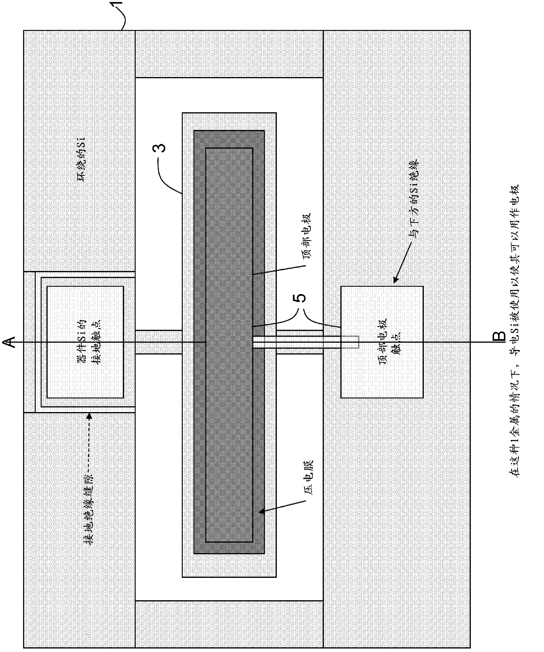
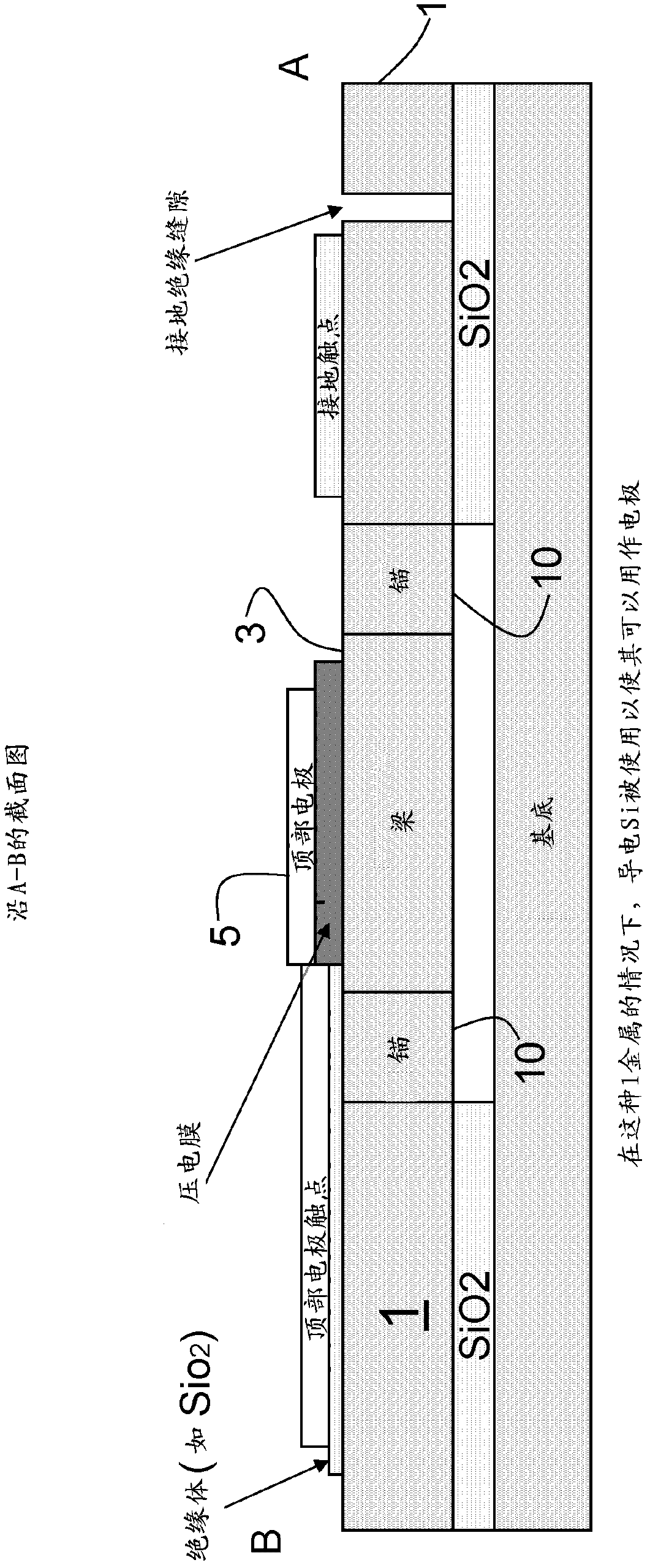
[0044] according to Figure 1 to Figure 4 , the invention relates to micromechanical structures in which a resonator 3 is suspended to a support structure 1 by means of anchors 10 . In a typical embodiment of the invention, the support structure 1 is a silicon device layer of an SOI (silicon on insulator) wafer. The dimensions and suspension of the resonator 3 are such that when the resonator 3 is excited by a corresponding electrical signal, the resonator 3 will move at a specific frequency f 0 vibration. The typical length of a beam resonator is 320 μm and its typical height is 20 μm. Excitation can be done capacitively by electrodes 5 formed on the resonator 3 and on the substrate 1, or alternatively, by Figure 2a or Figure 4 The piezoelectric structure is completed.

[0045] Electrical signals may be conducted to the structure through electrodes or by making the entire structure conductive to the electrical signal. Typical materials in resonators are Si for conduct...


PUM

PropertyMeasurementUnit
Sizeaaaaaaaaaa

Abstract

The invention relates to a micromechanical resonator comprising a substrate (1) of first material (2), a resonator (3) suspended to the supporting structure (1), the resonator (3) being at least partially of the same material (2) as the supporting structure and dimensioned for resonation at a specific frequency fo, coupling means (5) for initiating, maintaining and coupling the resonation of the resonator (3) to an external circuit (6), and the resonator (3) including second material (4), the thermal properties of which being different from the first material (2). In accordance with the invention the resonator (3) includes the second material (4) located concentrated in specific places of the resonator (3).

Description

technical field [0001] The invention relates to a micromechanical resonator according to the preamble of claim 1 . Background technique [0002] Thermal drift remains a major hurdle preventing silicon MEMS resonators from entering the quartz crystal oscillator market. This can be achieved by using materials such as amorphous SiO 2 To replace part of the resonance volume to achieve drift compensation. This impairs resonance performance compared to a pure single crystal resonator. [0003] Traditionally, by using a temperature compensating surround around the base silicon material (typically SiO 2 ), or alternatively, by using SiO 2 As part of a structure that is substantially uniformly distributed throughout the complete structure, problems associated with temperature drift of micromechanical resonators are resolved. For example, in the publication "Temperature compensation in silicon-based microelectromechanical resonators (temperature compensation in silicon-based micr...

Claims


Application Information

Patent Timeline
IPC IPC(8): H03H9/02H03H3/007H03H3/013B81B7/00B81B3/00
CPCH03H9/2463H03H9/2436B81B3/0081H03H3/0076H03H2009/02496H03H2009/02511H03H2009/241B81B2201/0271H03H2009/2442H03H9/02259H03H9/02338H03H9/02448H03H9/2452H03H2003/027H03H2003/0407H03H2009/02503
Inventor 阿尔内·奥亚图奥马斯·彭萨拉约翰纳·梅尔塔乌什
Owner TEKNOLOGIAN TUTKIMUSKESKUS VTT
Learn More